Creating and Running an Experiment
Overview
In this chapter, you’ll create a design matrix and run a model through a number of simulations that you set up in the experiment.
The sections in this chapter are:
Creating a Design Matrix
In this section, you’ll create a design matrix to measure the performance of the front spring rate. This section includes:
Promoting Factors
The first step required to creating your designed experiment is to select the factors that you want to include in your design matrix. You select factors from the Candidates list in the treeview, and then promote them to the Inclusions list. Promoting candidates to inclusions causes them to become part of your design matrix.
To promote factors from candidates to inclusions:
1. In the treeview, select the + in front of Factors. Factors expands to reveal Inclusions and Candidates.
2. Continue by expanding Candidates, properties, Front, achassis_gs_front_suspension, front_suspension, coil_spring, left, and achassis_gs_front_suspension_PA2_lsf. Under achassis_gs_front_suspension_pa2_lsf, you’ll see a list of design variables that you can include in your design matrix.
3. Select the candidate front_suspension_coil_spring_left_achassis_gs_front_suspension_PA2_lsf_rate. This is the front coil spring rate.
4. Move your cursor to the Adams Insight toolbar and select the Promote to inclusion tool  .
.
. The candidate front_suspension_coil_spring_left_achassis_gs_front_suspension_PA2_lsf_rate moves to the Inclusion list under Factors in the treeview.
Tip: | To select more than one factor, hold the Ctrl key as you click. To promote the factors directly from the treeview, press the shortcut key F5. |
The Factor form appears in the viewport as shown Figure 13.
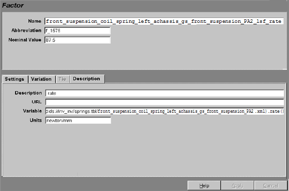
Figure 13 Factor Form
5. Set Abbreviation to spr_rate.
6. Select the Settings tab.
7. Enter -20,20 in the Settings text box, and then select Relative Percent as the Delta Type. This sets the spring rate to vary from 80% to 120% of its nominal value.
8. Select Apply.
9. Expand properties, Front, achassis_gs_front_suspension, front_suspension, stabilizer_bar, and achassis_gs_front_suspension_beamx_sta. Select the candidate achassis_gs_front_suspension_beamx_sta_diameter.
10. Leave the Settings at their default values to modify the stabilizer bar diameter ± 4 mm.
11. Promote the candidate.
12. To vary the front lower ball joint position, expand properties, Front, achassis_gs_front_suspension, front_suspension, lower_ball_joint, and then left.
13. Hold down the Ctrl key and select front_suspension_lower_ball_joint_left_x and front_suspension_lower_ball_joint_left_y. Promote these factors.
Promoting Responses
The next step in defining the design matrix is to select response variables.
To promote responses:
1. In the treeview, select the + in front of Responses.
The levels nested under Responses expand to reveal Inclusions and Candidates.
Hint: | You can select the minus (-) sign in front of Factors to collapse that section of the treeview and save screen space. |
2. Under Candidates, you’ll see a list of responses that are potential candidates you can include in your design matrix. Expand e_001_achassis_gs_full_sys_swpt and then select e_001_achassis_gs_full_sys_swpt_Roll_grad (for roll gradient) to display the Response form shown in Figure 14 below.
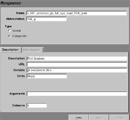
Figure 14 Response Form
3. In the treeview, hold down the Ctrl key and select e_001_achassis_gs_full_sys_swpt_Roll_grad and e_001_achassis_gs_full_sys_swpt_Understeer_grad (for understeer gradient), and promote both candidates.
The responses move from the Candidates to the Inclusion list.
Setting Design Specifications
You use the Design Specification form to specify the design objective and design type for the experiment.
To specify the design objective:
1. In the Adams Insight toolbar, select the Set design specification tool  , or in the treeview, expand the levels under Design, and then select Specification.
, or in the treeview, expand the levels under Design, and then select Specification. The Design Specification form appears in the viewport as shown next.
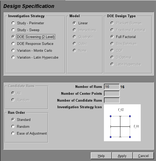
Figure 15 Setting Design Sepcification Form - DOE Screening (2 Level)
2. In the Design Specification form, make the following selections:
■Investigation Strategy: | DOE Response Surface |
■Model: | Quadratic |
■DOE Design Type: | CCF |
Use defaults for all remaining options.
3. Select Apply.
4. In the Adams Insight toolbar, select the Generate Work Space tool  , and verify the design matrix.
, and verify the design matrix.The Work Space appears in the viewport as shown in . This table displays the work space matrix for the experiment that you defined earlier in the tutorial. The factors and responses that you selected appear as column headings; the runs (called trials) appear as row headings.
In the treeview, at the Design level, the letters D:W appear to indicate that the Design contains a successfully generated design work space.
Note: | Columns appear in the design matrix in the order that you promote factors for inclusion. |
Tip: | Place your mouse pointer over column headings to display key information about the abbreviation shown. |
Running Your Experiment
Once you’ve verified the information in the Work Space, you’re ready to run the simulations. This section includes:
Saving the Experiment
Before returning to Adams Car you need to save the experiment and close Adams Insight.
To save the experiment:
1. Do one of the following:
■Select Save from the File menu
■Press Ctrl+S
■Select the Save to file button
2. Exit Adams Insight.
Using Adams to Build and Run Models
You use Adams Car to generate an Adams model (acf and adm files) that corresponds to each row in your design matrix. In this experiment, you create 28 models that correspond to the design matrix rows. Of the 28 runs, 25 are unique and the last three are duplicates of the first run.
To execute the models:
1. In Adams Car, in the property editor, select the Execute Investigation tab.
2. Verify that the following are selected:
♦Build Trials
♦Run Trials
♦Postprocess Trials
♦Load Responses
♦Launch Adams Insight
3. Use defaults for all other options.
4. Select Go.
The command window shows Adams Car building and running the 28 runs. Once execution completes, Adams Insight opens.