Creating and Running an Experiment
Overview
This chapter guides you through the process of creating a design matrix and running the model through a number of simulations that you set up in the experiment.
The sections in this chapter are:
Creating a Design Matrix
In this section, you’ll create a design matrix to measure the performance of the suspension model. This section includes:
Promoting Candidates
The first step required to creating your designed experiment is to select the factors that you want to include in your design matrix. You select factors from the Candidates list in the treeview, and then promote them to the Inclusions list. Promoting candidates to inclusions causes them to become part of your design matrix.
To promote factors from candidates to inclusions:
1. In the treeview, select the + in front of Factors. Factors expands to reveal Inclusions and Candidates.
2. Continue by expanding Candidates, tut_101_aview, ground, and hpl_tierod_outer. Under hpl_tierod_outer, you’ll see a list of design variables that you can include in your design matrix.
Note: | The treeview displays the full object hierarchy for each design variable. This tutorial will only refer to the variable name. For example, the variable hpl_tierod_outer.x appears as ground.hpl_tierod_outer.x in the treeview. |
3. Select the candidate, hpl_tierod_outer.x, and then move your cursor to the Adams Insight toolbar and select the Promote to inclusion tool  .
.
. The candidate hpl_tierod_outer.x moves to the Inclusion list under Factors in the treeview.
Tip: | To select more than one factor, hold the Ctrl key as you click. To promote the factors directly from the treeview, press the shortcut key F5. |
4. Continue promoting the following factors:
■hpl_tierod_outer.y
■hpl_tierod_outer.z
The factors move from the Candidates to the Inclusions list.
The factors appear in your treeview as shown in Figure 20.
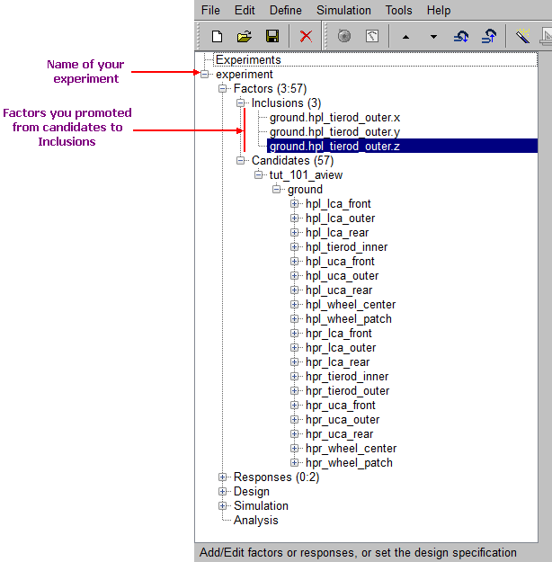
Figure 20 Treeview Showing Factors
Modifying Your Factors
After you promote your factors, you define parameters for them in the Factor form. To learn more about factor parameters, press the F1 key from the Factor form.
To modify your factors:
1. In the treeview, find the factors in the Inclusions list. Select the factor hpl_tierod_outer.x.
The Factor form appears in the viewport, as shown next.
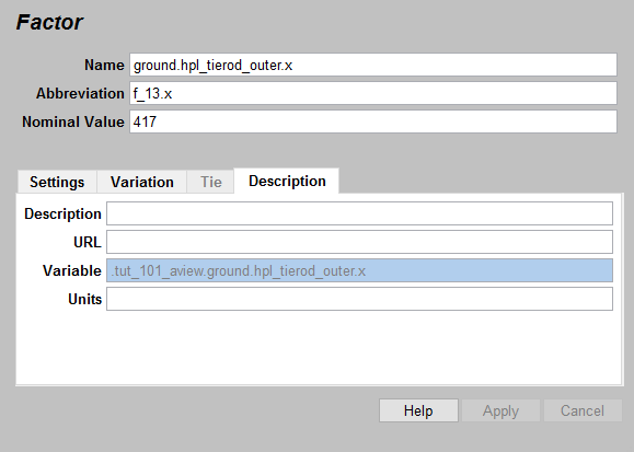
Figure 21 Factor Form
2. In the Factor form, set Abbreviation to tierod_outer.x
3. In the Description tab, set Units to mm.
The Units parameter is for annotation purposes. The units entered do not affect factor values.
4. In the Settings tab, enter the following:
■Type: | Continuous |
■Delta Type: | Relative |
■Settings: | -5, 5 |
5. Use the defaults for all remaining fields.
6. Select Apply.
Adams Insight saves your factor modifications.
7. Modify the parameters for the remaining factors, hpl_tierod_outer.y and hpl_tierod_outer.z, just as you did in step 2., above, using appropriate abbreviations for each.
Promoting Responses
Now that you have finished promoting and modifying your factors, the next step is to promote your responses for the experiment.
To promote responses from candidates to inclusions:
1. In the treeview, select the + in front of Responses.
The levels nested under Responses expand to reveal Inclusions and Candidates.
Tip: | You can select the minus (-) sign in front of Factors to collapse that section of the treeview and save screen space. |
2. Continue expanding the levels under Candidates and tut_101_aview. Under tut_101_aview, you’ll see a list of responses that are potential candidates you can include in your design matrix.
3. Select and promote the following responses just as you promoted the factors in step 3.:
■toe_left_REQ
■toe_right_REQ
The responses move from the Candidates to the Inclusion list.
Modifying Responses
The modifications you’ll make to the responses are minor. You’ll add units and change one of the parameters. To learn more about response parameters, press the F1 key from the Response form.
To modify responses:
1. In the treeview, under Responses, in the Inclusions list, select the response, toe_left_REQ.
The Response form appears, in the viewport, as shown next.
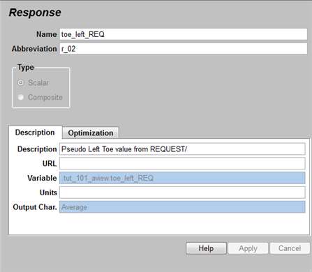
Figure 22 Response Form
2. In the Response form, enter or verify the following:
■Output Char.: | Average |
■Abbreviation: | toe_left_REQ |
■Units: | degrees |
Note: | Output characteristics are grayed out when you use Adams Insight with Adams View and other Adams applications. The output characteristic is set by the originating CAE application, and is displayed in the Response form for information only. |
Use the defaults for all remaining fields.
3. Select Apply.
Adams Insight saves your response modifications.
Setting Design Specifications
In this section, you’ll set the design objective and design type for your experiment. To learn more about setting design specifications, press the F1 key from the Design Specification form.
To specify your design objective:
1. In the Adams Insight toolbar, select the Set design specification tool  , or in the treeview, expand the levels under Design, and then select Specification. You can also select the Define menu, point to Experiment Design, and select Set Design Specification.
, or in the treeview, expand the levels under Design, and then select Specification. You can also select the Define menu, point to Experiment Design, and select Set Design Specification.The Design Specification form appears, in the viewport, as shown next.
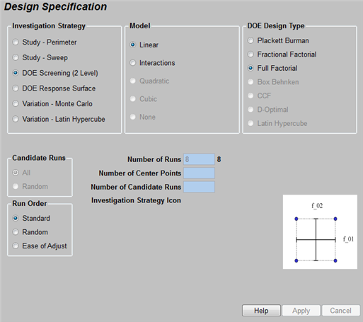
Figure 23 Design Specification Form - DOE Screening
2. In the Design Specification form, make or verify the following selections:
■Investigation Strategy: | DOE Screening (2 Level) |
■Model: | Linear |
■DOE Design Type: | Full Factorial |
Use defaults for all remaining options.
3. If you made any changes, select Apply.
4. Select the Define menu, point to Experiment Design, and then select Create Design Space.
5. Select the Define menu, point to Experiment Design, and then select Create Work Space.
 in the Adams Insight toolbar performs Steps
 The Work Space appears in the viewport as shown in . This table displays the work space matrix for the full-factorial experiment that you defined above. Adams View will run a simulation for each trial defined in this matrix. The column headings are sortable and sizeable. You can also select Work Space Review to view summary information for each factor and response in your experiment.
In the treeview, at the Design level, the letters D:W appear to indicate that the Design contains a successfully generated design work space.
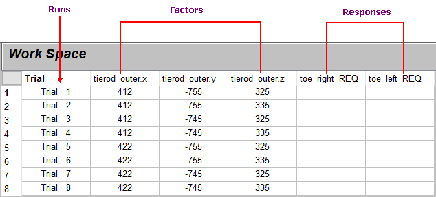
Figure 24 Work Space Matrix Before Running Trials in Adams View
Note: | Columns appear in the work space matrix in the order that you promote factors for inclusion. |
Tip: | Put your mouse pointer over column headings to display key information about the abbreviation shown. |
Running Your Experiment
Once you’ve verified the information in the Work Space, you’re ready to run the simulations.
To run the simulation:
1. In the Adams Insight toolbar, select the Run simulations tool  . You can also select the Simulation menu, point to Build-Run-Load, and then select All.
. You can also select the Simulation menu, point to Build-Run-Load, and then select All.Adams View opens and runs the simulations defined by your experiment. The Adams View Status bar displays messages showing simulation progress. The Message window also appears and displays warnings about joint locations, which you can ignore for this tutorial.
Note: | This procedure builds, runs, and postprocesses all of the simulations within the Adams View session. We recommend that you break up the process flow into its separate phases using the MDI INSIGHT BUILD and MDI INSIGHT LOAD commands. This is especially important when you have more than 30 trials. |
2. In the information box that appears, select OK.