Emag AT Results
Requests
■em_force_Operation_Point
♦Torque_1 – closest lower torque level for given Torque Demand
♦Torque_2 – closest higher torque level for given Torque Demand
♦WZ_rpm_1 – closest lower rpm level for actual rotor rpm
♦WZ_rpm_2 – closest higher rpm level for actual rotor rpm
♦Torque_demand – input for torque demand
♦Rotor_wz_rpm – actual rotor angular velocity in rpm units
♦Rotor_Pole_rel_angle – relative rotor pole angle against stator
♦State_ID – indication of motor operation mode
♦Rotor_wz_rad – actual rotor angular velocity in radian units
♦Rotor_Power – actual rotor power output
■em_force_Packet_Torque
♦Rotor_Pack_1 – resulting pack 1 torque
♦Rotor_Pack_2 – resulting pack 2 torque
♦.....
♦Rotor_Pack_n – resulting pack n torque
■em_force_Radial_Pole_Force
♦Rotor_Pack_1 – resulting rotor pole pack 1 radial force
♦Rotor_Pack_2 – resulting rotor pole pack 2 radial force
♦.....
♦Rotor_Pack_n – resulting rotor pole pack n radial force
♦Stator_Pack_1 – resulting stator pole pack 1 radial force
♦Stator_Pack_2 – resulting stator pole pack 2 radial force
♦.....
♦Stator_Pack_n – resulting stator pole pack n radial force
■em_force_Tangential_Pole_Force
♦Rotor_Pack_1 – resulting rotor pole pack 1 tangential force
♦Rotor_Pack_2 – resulting rotor pole pack 2 tangential force
♦.....
♦Rotor_Pack_n – resulting rotor pole pack n tangential force
♦Stator_Pack_1 – resulting stator pole pack 1 tangential force
♦Stator_Pack_2 – resulting stator pole pack 2 tangential force
♦.....
♦Stator_Pack_n – resulting stator pole pack n tangential force
■em_force_Resulting_Force_and_Torque
♦Rotor_FX – resulting force relative to rotor reference marker system
♦Rotor_FY – resulting force relative to rotor reference marker system
♦Rotor_FZ – resulting force relative to rotor reference marker system
♦Rotor_TX – resulting torque relative to rotor reference marker system
♦Rotor_TY – resulting torque relative to rotor reference marker system
♦Rotor_TZ – resulting torque relative to rotor reference marker system
♦Stator_FX – resulting force relative to stator reference marker system
♦Stator_FY – resulting force relative to stator reference marker system
♦Stator_FZ – resulting force relative to stator reference marker system
♦Stator_TX – resulting torque relative to stator reference marker system
♦Stator_TY – resulting torque relative to stator reference marker system
♦Stator_TZ – resulting torque relative to stator reference marker system
Extended Definition
Torque_1/ Torque_2 and WZ_rpm_1/ WZ_rpm_2
These values represent the closest levels of torque reps. rotor angular velocity selected from available data for magnetic force definition, see Figure 35. Based on these values the actual forces acting on rotor and stator are calculated for requested torque demand and actual rotor angular velocity.
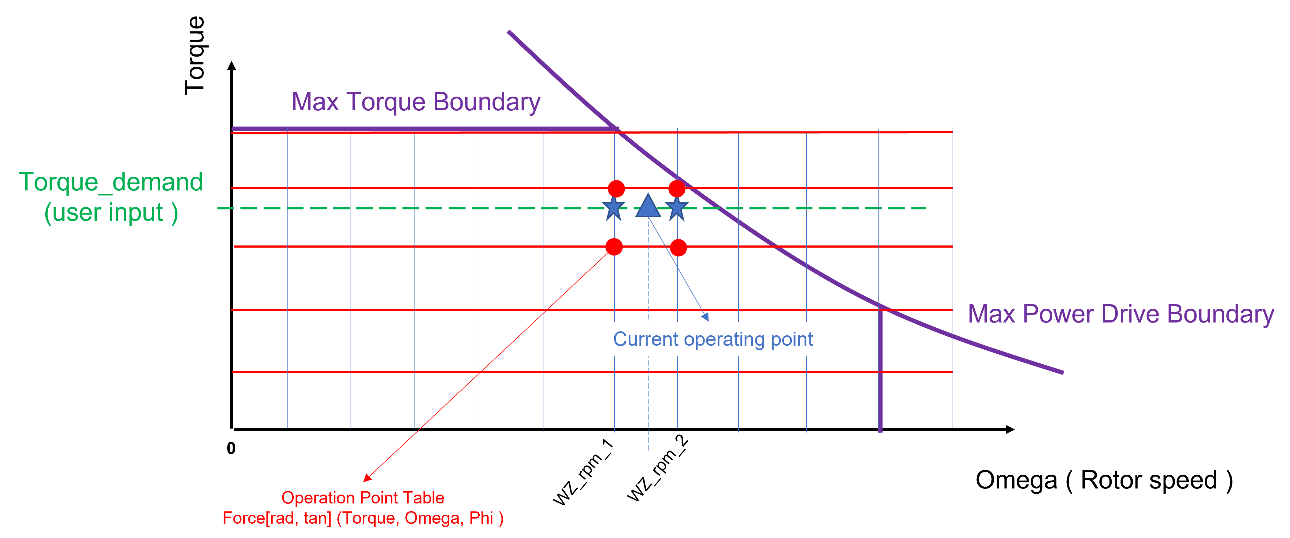
Figure 35 Closest Torque and Angular velocities levels
Rotor_Pole_rel_angle
The value represents relative angle of rotor pole with respect to virtual stator pole portion. In magnetic field simulation, usually only one rotor pole and corresponding stator portion are considered. The relative pole angle is limited to angular value corresponding to one pole of rotor. The relation between absolute rotor angle and relative pole angle is shown in Figure 36.

Figure 36 Relative Pole angle and Absolute rotor angle
State_ID
The value represents current operation mode of electric motor, for relation between id value and motor mode see Figure 37
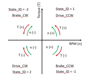
Figure 37 State ID and operation mode relation
Pole forces
The radial and tangential pole forces are calculated per each rotor pack on rotor and corresponding pack portion on stator. The radial force represents perpendicular component of magnetic field force acting on corresponding surface on rotor resp stator teeth surface and windings. The radial force tends to eliminate the air gap between rotor and stator. The tangential force represents component of magnetic field force imposing the rotation of rotor. The axial component of magnetic field is not considered. The surface belonging to one rotor pole per rotor pack is illustrated for rotor and stator in figure Figure 38
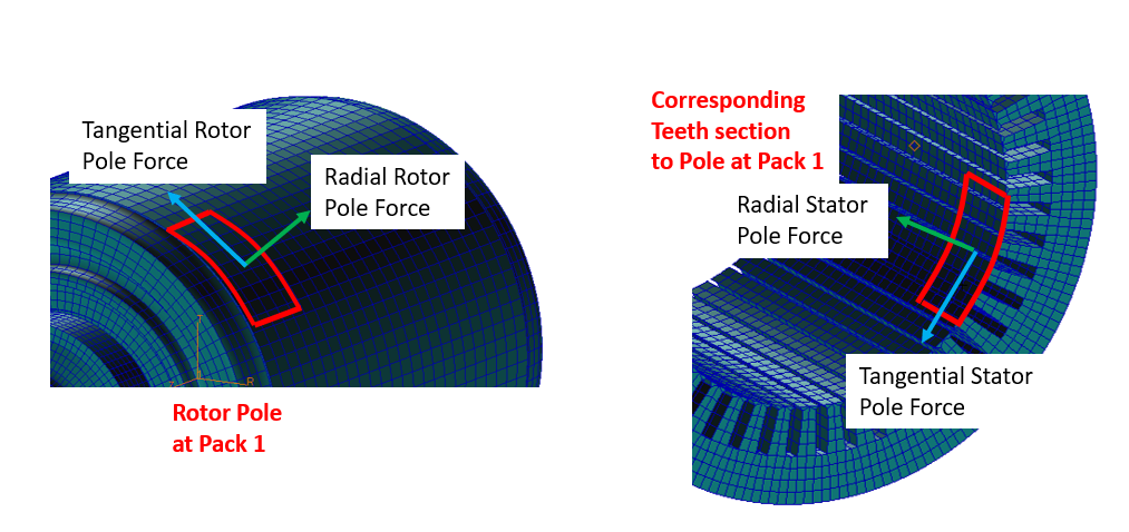
Figure 38 Surface of rotor pole per rotor pack for stator and rotor
Local Reference System
The components of request Resulting Force and Torques are calculated relative to local reference system of rotor reps. stator, see Figure 39. The reference system is located on rotational axis and the half of active stator resp. rotor length/width forming the air gap between rotor and stator. For detailed information about location of reference system see section create Emag AT Force.
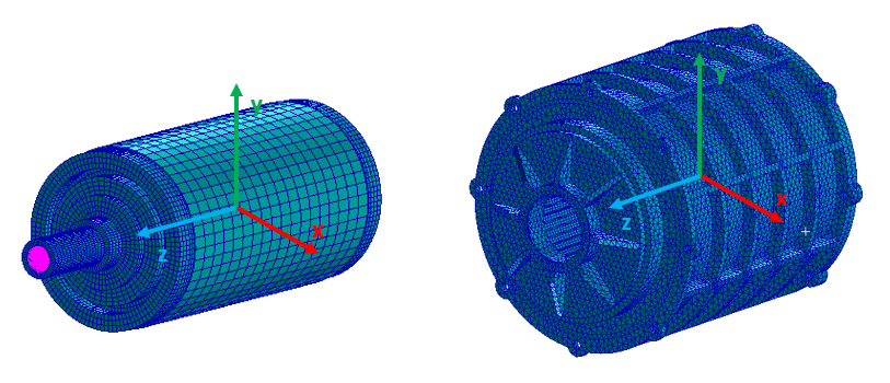
Figure 39 Local reference system on stator and rotor