Requests
The results are reported in element coordinate system (ECS). Each screw element has such coordinate system as shown in Figure 356. The origin of the ECS is located at the reference marker of screw element. The Z-axis of the ECS is identical with the Z-axis of screw. The Y-axis of the ECS points to thread tip middle in axial cross section. The X-axis follows from right-hand rule. Due to automatic orientation in assembly process usually the nut is rotated to mesh with the spindle, in this case the ECS is not identical with reference marker, there is difference in X and Y axis direction
It is assumed, that all starts of screw are in contact.
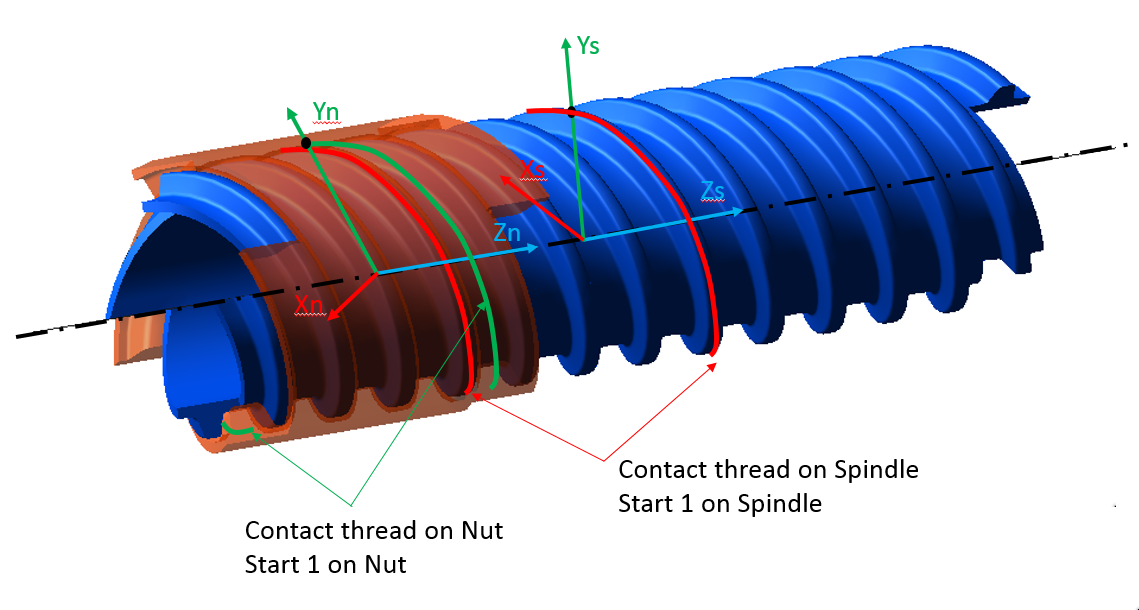
Figure 356 Element coordinate system
There are following request groups and underlying requests for Standard option of the Flexible Tooth:
■Kinematics
■Misalignment_DX
■Misalignment_DY
■Misalignment_DZ
■Misalignment_AX
■Misalignment_AY
■Misalignment_Magnitude
■Power Loss
■Friction
■Total
■Power_Nut
■Power_Spindle
■Efficiency
■Total Force and Torque
■FX, FY, FZ_Nut
■TX, TY, TZ_Nut
■FX, FY, FZ_Spindle
■TX, TY, TZ_Spindle
■Tooth_0
■Tooth_1
■Tooth_2
■Tooth_3
There are following request groups and underlying requests for Enhanced option of the Flexible Tooth:
■Friction
■FX, FY, FZ_Nut
■TX, TY, TZ_Nut
■Tooth_0_Sliding_Vel
■Tooth_1_Sliding_Vel
■Tooth_2_Sliding_Vel
■Tooth_3_Sliding_Vel
■Tooth_0_Fm_Frict
■Tooth_1_Fm_Frict
■Tooth_2_Fm_Frict
■Tooth_3_Fm_Frict
■Tooth_0_Tz_Frict
■Tooth_1_Tz_Frict
■Tooth_2_Tz_Frict
■Tooth_3_Tz_Frict
■Kinematics
■Contact_Tooth_Nut
■Contact_Tooth_Spindle
■Relative_WZ
■Relative_VZ
■Stiffness
■FX, FY, FZ_Nut
■TX, TY, TZ_Nut
■Tooth_0_Max_Penetration
■Tooth_1_Max_Penetration
■Tooth_2_Max_Penetration
■Tooth_3_Max_Penetration
Extended definition:
The result of Contact_Tooth_Nut and Contact_Tooth_spindle is explained on Figure 357. If the right flank is in contact, the tooth number is displayed as negative number. The tooth and thread are used as synonyms in this chapter.
The result of Misalignment _DX, Misalignment _DY, Misalignment_DZ, Misalignment_AX, Misalignment_AY, Misalignment_Magnitude gives the position and the rotation around the X-axis and Y-axis of spindle relative to nut in the ECS of nut.
The result of Tooth_x_Max_Penetration helps to evaluate the selected contact stiffness for rigid body contact. In case of a flexible tooth, only a small penetration should be reported under normal operating conditions. The tooth_0 is the first start of the screw. The relative teeth numbers 0 to +2 (0, P1, P2, P3, Pn) follow the rule of right hand when the thumb points in screw Z-axis direction; see Figure 434 for the definition of the contact tooth and for screw teeth numbering convention.
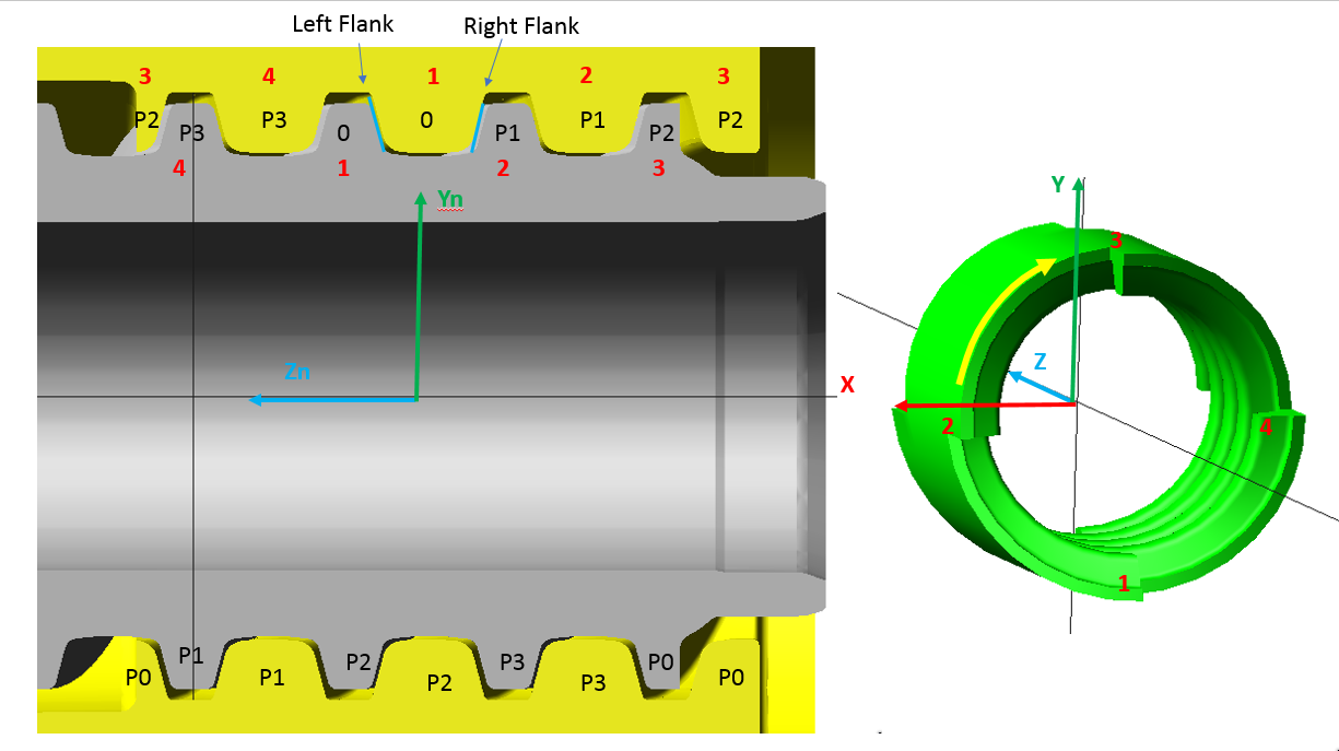
Figure 357 Contact tooth/thread and numbering convention
The resulting force and torque vectors, which are measured in the ECS and applied on nut are given by FX, FY, FZ_Nut and TX, TY, TZ_Nut. The corresponding force and torque vectors applied on screw can be plotted as FX, FY, FZ_Spindle and TX, TY, TZ_Spindle. The resulting force and torque vectors including all components from contact, damping and friction are located in the Total Force and Torque result group.
The result of Tooth_x_Sliding_Vel expresses the maximum magnitude of sliding velocity vector over the thread contact area. The friction force magnitude per tooth Tooth_x_Fm_Frict and friction torque magnitude per tooth Tooth_x_Tz_Frict follow from Coulomb friction law.
The Relative WZ and Relative VZ in Kinematic group are the relative rotational and translational velocities of Nut against the Spindle.