Create Bearing
This icon launches the Create Bearing wizard from which the following combination of bearing modeling methods and types can be created:
Joint
The Joint method represents bearings as ideal kinematic joints and allows the user to specify friction and motion directly from the wizard.
■Radial: An Adams cylindrical joint is used to connect two parts. It prevents translation along, and rotation about, the two radial axes.
■Radial and Thrust: An Adams revolute joint is used to connect two parts. It prevents translation along, and rotation about, the two radial axes. And, it prevents axial translation therefore bearing the thrust load.
Compliant
In the compliant method, a force is used to represent the bearing. Simple linear stiffness and damping terms can be applied (axial and symmetric radial terns) all the way up to full 6x6 stiffness and damping matrices. This method is useful when the effects of bearing compliance must be considered.
Clearance
The Clearance method represents six-component force (gforce) to represent three different types of clearance bearing. The three types are 'Radial', 'Radial Axial' and 'Axial'. The bearing formulation is based on values obtained from Timken Company manual (for free online resources register at http://www.timken.com/timken_ols/bearings/). The running torque equations are for bearings whose torque has stabilized after a period of running under operating conditions, so called a "running" bearing. The equations apply to bearings lubricated with circulating oil or oil level systems. You can use the equations to model all single-row bearing loading conditions.
Adams calculates the force and torque for the bearing using backlash expressions. The force or torque is almost zero until the relative translational or angular displacement is lower than the specified lash, then the force or torque follows an elastic law.
For 'Axial' bearings, the thrust force acts only along one direction (z-positive), being zero along the other.
The reaction forces in the three translational directions are defined with a linear stiffness + backlash. The two cardanic reaction torques are calculated based on the translational forces and the geometric properties (bearing diameter).
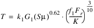
To calculate the running torque of the bearing, depending on several factors (bearing geometry, applied loads, load zone, speed of rotation, and so on) the following expressions have been used:
Radial load or combined radial thrust load:
Pure thrust load:
where:
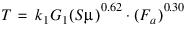
■T = Running torque
■k1 = Constant being 2.56e-5 for T in N*m, 3.54e-5 for T in lbf*in
■G1 = Bearing geometry factor
■S = Running speed (rpm)
■ = Lubricant viscosity (Cp)
= Lubricant viscosity (Cp)■K = Bearing K-factor. The K-factor is the ratio of basic dynamic radial load rating to basic dynamic thrust load rating of a single row bearing.
■f1 = Combined load factor. The combined load factor can be read from Timken tables as a function of (K*Fa)/(Fr).
■Fr = Radial load
■Fa = Thrust road
Detailed
The Detailed method uses a six-component force (gforce) to represent fourteen different types of rolling element bearings within the families of ball bearings, cylindrical roller bearings, needle roller bearings, spherical roller bearings and tapered roller bearings as listed below.
■Deep Groove Ball Bearing Single Row
■Deep Groove Thrust Ball Bearing One Sided
■Angular Contact Ball Bearing Single Row
■Four Point Bearing
■Cylindrical Roller Bearing Single Row
■Cylindrical Roller Bearing Single Row Full Complement
■Cylindrical Roller Bearing Double Row
■Cylindrical Roller Bearing Double Row full Complement
■Axial Cylindrical Roller Bearing
■Needle Roller Bearing with/without internal ring
■Needle Cage
■Tapered Roller Bearing Single Row
■Spherical Roller Bearing
■Axial Spherical Roller Bearing
■Deep Groove Ball Bearing Double Row
■Thrust Needle Cage
This force has a stiffness component (returned by the KISSsoft calculation) and a damping component calculated by Adams. The stiffness component is calculated at every step based on the positions at the bearing location. The damping coefficient is determined by multiplying the square root of the instantaneous stiffness by a user-entered damping factor. Details regarding the KISSsoft calculation are provided below:
Roller Bearing
Rolling bearings are available in many shapes and varieties, each with its own distinctive features. Roller bearings have certain advantages when compared with sliding bearings:
■The starting torque or friction is low. The difference between the starting and running torque or the difference between starting and dynamic friction is small.
■Roller bearings are internationally standardized and due to this they are readily available and interchangeable.
■Roller bearings are easy to lubricate and their lubricant consumption is very low.
■Many roller bearings can carry both radial and axial loads simultaneously.
■Roller bearings can be used in either high or low temperature applications.
■Roller bearings rigidity can be improved by providing a negative clearance by preloading.
To calculate the service life and load capacity of roller bearings, certain methods are included in manufacturer catalogs.
Below table is the comparison of Ball and Roller bearings:
Bearings | |
|---|---|
Ball | Roller |
Ball bearings will have point contact with raceway. The contact surface will be oval when a load is applied. | Roller bearings will have linear contact with raceway. The contact surface will be rectangular when a load is applied. |
The rolling resistance will be low due to point of contact with raceway. They are more suitable for low torque and high speed applications. | The torque and rigidity are higher for roller bearings when compared to ball bearings due to its linear contact with raceway. |
The load carrying capacity of ball bearings are low. The radial bearings can carry both radial and axial loads. | The load carrying capacity of roller bearings are quite high when compared to ball bearings. They can carry radial and/ or bi-directional axial loads depending upon their configurations and arrangements. |
Classification and Characteristics of Rolling Bearings
In general, rolling bearings may be classified as radial or thrust bearings according to bearing design or they may be classified as ball or roller bearings according to the type of rolling element. Radial bearings are mainly designed for supporting a load perpendicular to a shaft axis, whereas thrust bearings accept loads parallel to the shaft axis.
Two main classifications of rolling bearings are:
Ballbearings
Ball bearings can be further divided according to the number of rows into either single-row or double-row (for Thrust Ball bearings, single-direction and double-direction.) Ball bearing may be still further sub-divided into smaller segments according to the relationship between the bearing rings and rolling elements; the shape of bearing rings; and use of accessories.
Roller bearings
Roller bearings are classified according to the shape of the rollers; cylindrical, needle, tapered and spherical.
Other classification methods include:
■Number of rolling rows (single, double, or 4-row)
■Separable and nonseparable, in which either the inner ring or the outer ring can be detached.
There are also bearings designed for special applications, such as: railway car journal roller bearings, ball screw support bearings, turntable bearings, as well as linear motion bearings (linear ball bearings, linear roller bearings and linear flat roller bearings)
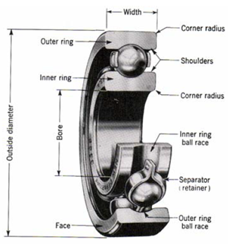
Rolling bearing construction
Most rolling bearings consist of rings with raceway (inner ring and outer ring), rolling elements (either balls or rollers) and cage. The cage separates the rolling elements at regular intervals, holds them in place within the inner and outer raceways, and allows them to rotate freely.
Raceway (inner ring and outer ring) or raceway washer)
The surface on which rolling elements roll is called the "raceway surface" ("raceway washer"). The load placed on the bearing is supported by this contact surface. Generally the inner ring ("shaft raceway washer") fits on the axle or shaft and the outer ring ("housing raceway washer.") on the housing.
Rolling elements
Rolling elements classify in two types: balls and rollers. Rollers come in four types: cylindrical, needle, tapered and spherical. Balls geometrically contact with the raceway surfaces of the inner and outer rings at "points", while the contact surface of rollers is a "line" contact. Theoretically, rolling bearings are so constructed as to allow the rolling elements to rotate orbitally while also rotating on their own axes at the same time.
Cages
Cages function to maintain rolling elements at a uniform pitch so load is never applied directly to the cage and to prevent the rolling elements from falling out when handling the bearing. Types of cages differ according to way they are manufactured, and include pressed, machined and formed cages.
Characteristics of the most important bearing types
Deep Groove Ball Bearings
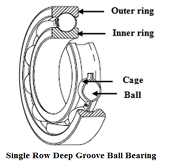
Deep Groove ball bearings are the most popular. The single row radial grooved ball bearing is the most commonly used, because it is both extremely versatile and inexpensive. The bearing ring grooves are circular arcs made slightly larger than the radius of the ball. The balls make point contact with the raceways. Deep Groove ball bearings can sustain radial, axial, or composite loads and because of simple design, this bearing type can be produced to provide both high-running accuracy and high-speed operation.
Single Row Angular Contact Ball Bearings
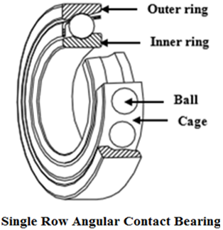
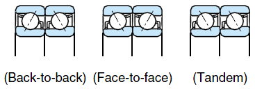
Each ring of a self-holding single row angular contact ball bearing has one lower shoulder and one higher shoulder. The grooves on the higher shoulder are positioned so that the pressure angle is normally 40o. These bearings are non-separable. Since the balls are inserted utilizing counter-bore construction, a larger number of balls can be installed than in the case of Deep-groove ball bearings. The higher number of rollers in this configuration means it can withstand not only radial forces but also larger axial forces in one direction than grooved ball bearings. This must be taken into account when sizing the bearing. Single-row Angular Contact ball bearings can sustain radial, axial or composite loads, however, any axial load must be in one direction. Because of its one-sided axial loading capacity, these types of bearings are usually installed in pairs where the second one is mounted in the opposite direction. Combination or paired bearings can be arranged BACK-TO-BACK, FACE-TOFACE, or in TANDEM
Double Row Angular Contact Ball Bearings
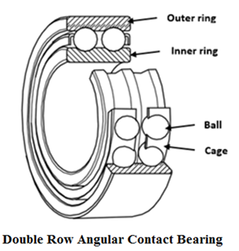
The double row angular contact ball bearing is similar to the adjacent, BACK-TO-BACK mounting of two Single-row Angular Contact ball bearings. Because fewer balls can be inserted per row compared to Single-row Angular Contact ball bearings, a Double-row Angular Contact ball bearing will have less load capacity than an equivalent Back -to- Back set of two Single-row Angular Contact ball bearings. This bearing type can sustain radial, moment and bi-directional axial loads.
Self-Aligning Ball Bearings
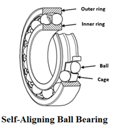
This self-aligning ball bearing is a double row bearing with the inner ring and ball assembly contained within an outer ring which has a spherical raceway. Due to the construction, this bearing type will tolerate a small angular misalignment from deflection or mounting error.
Self-aligning Ball bearings are suitable for long shafts where accurate positioning of housing bores is difficult. This bearing should only be used in light axial load applications due to the small axial support of the rolling elements by the outer ring raceway.
Cylindrical Roller Bearings
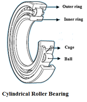
Construction of this roller bearing type is the simplest of all radial roller bearings. This bearing type is often used in high-speed applications. It can support larger radial loads than ball bearings of the same size because the inner ring, outer ring, and rollers are in line contact. There are various cylindrical roller bearing configurations based on the type of rim (N, NJ, NU, NH, NP, NN, and NNU) available. The inner and outer rings can be separated to facilitate assembly, and both can be fit with shaft or housing tightly. It there is no ribs, either the inner or the outer ring can move freely in the axial direction.In the case where there is a ribs, the bearing can bear a slight axial load between the end of the rollers and the ribs.
Needle Roller Bearings
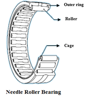
Needle roller bearings are a special type of cylindrical roller bearing. There are numerous types available and are available with or without an inner ring. There are also cage and roller assemblies without rings but they have relatively high radial loads. A cage will keep needle rollers separated by a distance and parallel to each other. Needle bearing rollers are longer and small in diameter than cylindrical rollers.
Note: | The crowning is considered by using the default profile function as specified in the ISO 16281. |
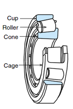
Tapered Roller Bearings
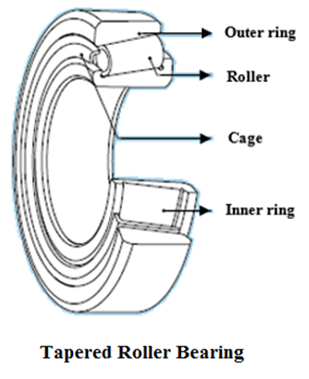
The ring races of this type of bearing are made with a taper so that the planes of the surfaces of the raceways and roller axis meet at a point. Due to the angle of the race, a radial force produces an axial reaction force. The detachable outer ring makes them easy to assemble and dismantle. A single-row Tapered roller bearing can support a combined radial and axial load. If either a radial load or bi-directional axial load is to be carried, a pair of bearings must be used in a "face-to-face" or "back-to-back" position.
Tapered roller bearings are separable into the following components:
■Outer ring
■Inner ring
■Roller assembly
The nonseparable part that is, inner ring and roller assembly is termed as "Cone" and the outer ring is termed as "Cup". Internal clearance during mounting could be provided by positioning cone relative to cup axially
Spherical Roller Bearings
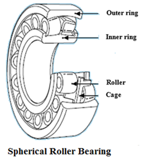
Spherical bearings have barrel-shaped rollers between the inner ring, which has two raceways, and the outer ring which has one spherical raceway. They are self-aligning in a manner similar to that of self-aligning ball bearings, since the center of curvature of the outer ring raceway surface coincides with the bearing axis. Due to this, it will tolerate a small angular misalignment from deflection or mounting error. It can take not only heavy radial loads, but also some axial loads in either direction. They are suitable for use where there are heavy or impact loads due to its excellent radial load carrying capacity. Some bearings have tapered bores and may be mounted directly on tapered shafts or cylindrical shafts using adapters or withdrawal sleeves.
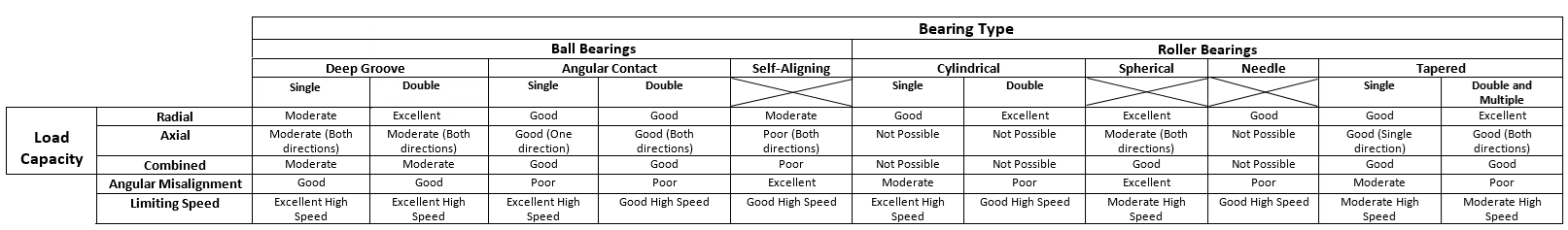
Bearing Characteristics
Bearing types are selected according to the types of load (radial, axial, combined, moment) and the magnitude of these loads on the bearing. Below table outlines the types of load and applicable bearing types. In bearings of identical dimensional series, a roller bearing will have a greater load rating capacity than a ball bearing.
Roller Bearing Internal Geometry
Deep groove ball bearing (single row), four-point contact bearing:
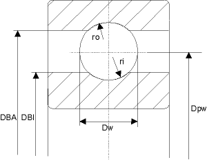
Dimensions of deep groove ball bearings:
■No. of balls = Z [-]
■Ball diameter = DW [mm]
■Reference diameter = DPW [mm]
■Rim diameter inside, pressure side = DBI [mm]
■Rim diameter outside, pressure side = DBA[mm]
■Radius of curvature, inside = ri [mm]
■Radius of curvature, outside = ro [mm]
Note: | DBA, DBI not used. |
Deep groove ball bearing (Double row):
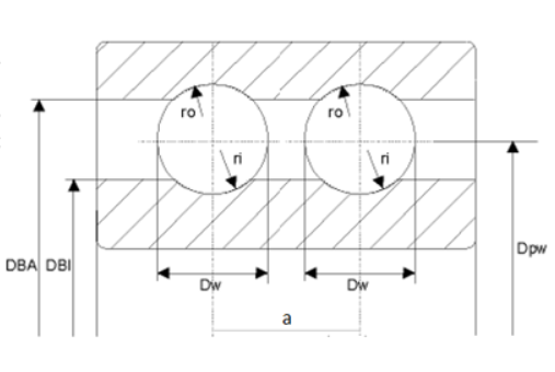
Dimensions of deep groove ball bearings:
■No. of balls = Z [-]
■Ball diameter = DW [mm]
■Reference diameter = DPW [mm]
■Rim diameter inside, pressure side = DBI [mm]
■Rim diameter outside, pressure side = DBA[mm]
■Radius of curvature, inside = ri [mm]
■Radius of curvature, outside = ro [mm]
■Ball Centerline Distance = a [mm]
Note: | DBA, DBI not used. |
Angular contact bearing (single row):
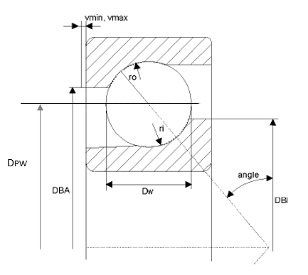
Dimensions of the angular contact bearing:
■No. of balls = Z [-]
■Ball diameter = DW [mm]
■Reference diameter = DPW [mm]
■Rim diameter inside, pressure side = DBI [mm]
■Rim diameter outside, pressure side = DBA[mm]
■Radius of curvature, inside = ri [mm]
■Radius of curvature, outside = ro [mm]
■Minimum inside tension = vmin [mm]
■Maximum inside tension = v max [mm]
Note: | vmin.max not used. |
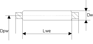
Cylindrical roller bearing (single row), (single row, full complement):
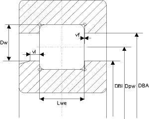
Dimensions of cylindrical roller bearings
■No. of rollers = Z [-]
■Roller diameter = DW [mm]
■Reference diameter = DPW [mm]
■Rim diameter inside pressure side = DBI [mm]
■Rim diameter outside pressure side = DBA [mm]
■Roller length = Lwe [mm]
■Axial displacement floating bearing = vl [mm]
■Axial displacement fixed bearing = vf [mm]
Tapered roller bearing (single row):
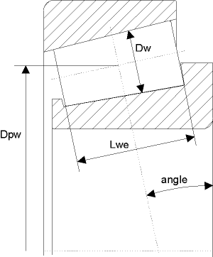
Dimensions of tapered roller bearings:
■No. of rollers = Z [-]
■Roller diameter = Dw [mm]
■Reference diameter = Dpw [mm]
■Roller length = Lwe [mm]
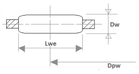
Spherical roller bearings:
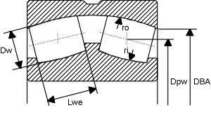
Dimensions of spherical roller bearings
■No. of balls = Z [-]
■Pin diameter = Dw [mm]
■Reference diameter = Dpw [mm]
■Rim diameter inside, pressure side = DBI [mm]
■Rim diameter outside, pressure side = DBA [mm]
■Radius of curvature, inside = ri [mm]
■Radius of curvature, outside = ro [mm]
Note: | DBA, DBI not used |
Needle roller bearing and Needle cage:
Dimensions of needle roller bearings/needle cages:
■Number of rollers = Z [-]
■Pin diameter = Dw [mm]
■Reference diameter = Dpw [mm]
■Roller length = Lwe [mm]
Thrust Needle Cage
Dimensions:
■Number of rollers = Z [-]
■Pin diameter = Dw [mm]
■Reference diameter = Dpw [mm]
■Roller length = Lwe [mm]
Axial cylindrical roller bearing:
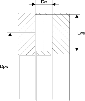
Dimensions of axial cylindrical roller bearings:
■No. of rollers = Z [-]
■Roller diameter = Dw[mm]
■Reference diameter = Dpw [mm]
■Roller length = Lwe [mm]
Axial spherical roller bearings:
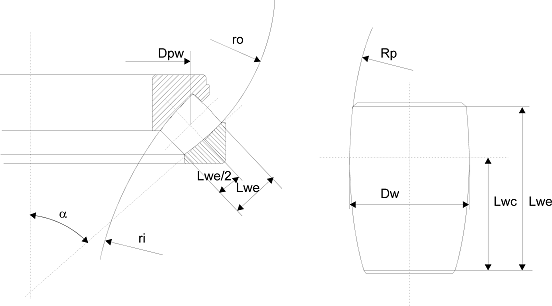
Dimensions of axial spherical roller bearings
■Number of pins = Z [-]
■Pin diameter = Dw [mm]
■Reference diameter = Dpw [mm]
■Roller length = Lwe [mm]
■Distance to roller crown = Lwc [mm]
■Radius of curvature, inside = ri [mm]
■Radius of curvature, roller = Rp [mm]
■Radius of curvature, outside = ro [mm]
Bearing Internal Clearance and Preload
Bearing internal clearance
Bearing internal clearance is the amount of internal free movement before mounting. When either the inner ring or the outer ring is fixed and the other ring is free to move, displacement can take place in either an axial or radial direction. This amount of displacement (radially or axially) is termed the internal clearance and, depending on the direction, is called the radial internal clearance or the axial internal clearance.
Internal clearance selection
The internal clearance of a bearing under operating conditions is usually smaller than the same bearing's initial clearance before being installed and operated due to several factors including bearing fit, the difference in temperature between the inner and outer rings and so on. Bearing's operating clearance has an effect on bearing life; care must be taken in selecting the most suitable operating clearance.
Successful bearing performance depends on having the appropriate operating clearance to avoid premature bearing damage and reduced fatigue life.
Criteria for selecting bearing internal clearance
A bearing's life is theoretically maximum when operating clearance is slightly negative at steady operation. In reality it is however difficult to constantly maintain this optimal condition. Bearing life will decrease if temperature increases due to increase in negative clearance due to fluctuation in operating conditions such as;
■When the inner ring is expanded or the outer ring is compressed due to a tight fit of the bearing;
■When the inner ring expands even more due to the operating temperature - This is often the case.
Therefore in general bearing operating in an ordinary circumstances, it is recommended to select an initial internal clearance where the operating clearance is slightly larger than zero. Normal clearance selection enables you to obtain proper operating clearance for normal rotational speed and ordinary operating temperature. Bearing clearance C2 or C1 is used where a very rigid shaft guidance is required where bearings often run under preload. A larger-than-normal bearing clearance is selected for tighter fits and/or a great temperature difference between inner ring and outer ring.
Depending on the bearing type, either the radial or the axial bearing clearance is decisive. It is standardized and classified into different clearance groups (C); which allows the determination of the required bearing clearance for the wide range of fits and operating conditions.
Clearance Group Suffix | Bearing Clearance |
|---|---|
C1 | Smaller than C2 |
C2 | Smaller than normal |
CN | Normal |
C3 | Larger than normal |
C4 | Larger than C3 |
Bearing Preload
In general, bearings are operated with a certain amount of clearance. However, there are applications where bearings are given an initial load; the bearings internal clearance is negative before operation and this is termed as preload. It is generally applied to angular ball bearings and tapered ball bearings.
Some of the typical reasons for using bearing preload are as follows:
■To improve bearing stiffness and rigidity; Internal clearance provides for an accurate gear mesh
■To minimize a noise due to vibrations.
■To prevent a bearing from spinning freely with a single direction high axial load.
■It is suitable for high rotation speed due to increase in particular bearing frequency
■Running accuracy and precision could be improved by eliminating clearances and reducing deflections.
Care should be taken while applying excessive preload as it could result in reduction of life, abnormal heating, or increase in torque. Therefore one should consider the objectives before determining the amount of preload.
Bearing Selection Process
Generally, bearing type is chosen based on factors such as operating conditions, mounting arrangements, cost, space etc. Once you know the bearing operating conditions and performance, choose the size of the bearing to satisfy the desired life requirement. In addition to fatigue life, it is also necessary to consider other factors such as lubricant, wear etc. There is no fixed procedure available for bearing selection but the following steps gives you some general information about the bearing selection procedure.
■Determine the operating conditions of the bearings (Speed, Loads, Misalignment….)
■Based on the above operating conditions and performance, select a suitable bearing type (Mounting arrangements, Load direction…)
■Select a bearing size based on expected life, Load carrying capacity.....…
■Decide whether the standard or extra precision accuracy is required and select a suitable bearing class based on torque, stability, accuracy…
■Determine and select required internal clearance, preload and so on.
■Select required type and material of bearing cage based on parameters such as speed, loads and so on.
■Select required type (Grease or oil) and method of lubrication
■Determine the constraints influencing mounting and dismounting procedures.
■Prepare a final specification related bearing and its surrounding parts.
Load Ratings
Basic load ratings are a standardized measure provided by the bearing industry to quantify the rolling element bearing's ability to resist bearing failure.
It reflects the load carrying capacity of bearings and is an important factor in the dimensioning of rolling bearings. It is determined by the number and size of the rolling elements, Pitch circle diameter of bearing etc. The load ratings of roller bearings are higher than those of ball bearings due to the larger contact area between rollers and raceways. The load rating of a radial bearing is defined for radial loads whereas that of a thrust bearing is defined for axial loads. Every rolling bearing has a dynamic load rating and a static load rating. The terms "dynamic" and "static" refer to the bearing movement but not to the type of load. In all rolling bearings with a curved raceway profile, the radius of the raceway is slightly larger than that of the rolling elements.
Fatigue Load Limit (Cu):
This is the load below which fatigue will not occur in the bearing. It is calculated for ideal conditions based on formulas in ISO 281. Generally, it is the load that produces a contact stress between the roller or ball and raceway of 1,500 MPa
Dynamic Load Rating (C0):
It is a factor for the load carrying capacity of a rolling bearing under dynamic load at which the bearing rings rotate relative to each other. It is the load which is constant in magnitude and direction, a rolling bearing can theoretically accommodate for a nominal rating life of 1 million revolutions. It is generally, determined by bearing geometry, number and size of balls, bearing pitch diameter, and ring and ball material. This load rating is used in conjunction with the actual applied radial load to calculate bearing fatigue life.
Static Load Rating (C):
The static load rating is a load acting on a stationary rolling bearing which causes, at the centre of the contact area between the most heavily loaded rolling element and the raceway, a total plastic deformation of 0.01% of the rolling element diameter at the most heavily loaded contact area. It is affected by material, number and size of balls, raceway curvatures, raceway depths, and contact angles
For the normal curvature ratios this value corresponds to a Hertzian contact pressure of about
■4000 N/mm2 for roller bearings
■4600 N/mm2 for self - aligning ball bearings
■4200 N/mm2 for all other ball bearings
Note: | Generally, for a given bearing, a change in the pitch circle can impact the dynamic load rating, and a change in the ball diameter or ball quantity can impact both load ratings. When compared to the original configuration, changing all of these parameters (ball diameter and so on.) at the same time (it depends on what the actual changes are) can result in the dynamic capacity moving in one direction and the static capacity moving in the opposite direction. |
Bearing Service Life
When bearings rotate, the inner and outer rings and rolling elements are constantly loaded. This produces material fatigue and eventually bearing failure. Life of individual bearings varies considerably, even if they are of the same size, same material, same heat treatment and are under the same operating conditions. In general, it is the life during which the bearing operates reliably and. T the fatigue life of a bearing is the upper limit of the service life. Often this limit is not reached due to wear or lubrication breakdown. The life of dynamically stressed rolling bearings, is the operating time until failure due to material fatigue. By means of the classical calculation method, a comparison calculation, the nominal rating life L or Lh of a bearing is determined; further AMachinery will calculate, the enhanced life Lna or Lhna taking into account bearing lubricants and so on.
Nominal Service Life (L)
The standardized calculation method for dynamically stressed rolling bearings is based on material fatigue as the cause of failure. The life formula L10, is the nominal rating life in millions of revolutions which is reached or exceeded by at least 90% of a large group of identical bearings.
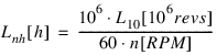
Nominal Service Life in Hours (Lnh)
The nominal rating life applies to bearings made of conventional rolling bearing steel and the usual operating conditions that is, good lubrication, no extreme temperatures, normal cleanliness and so on. The bearing life can be expressed in hours as below:
Lh10 = Lnh = L * 106 / n*60
Lnh - is the nominal rating life in millions of revolutions which is reached or exceeded by atleast 90% of a large group of identical bearings.
Nominal Reference Life:
This adjusted rating life calculation takes into account, in addition to the load, failure probability (a1) and other significant operating conditions ((aISO) The life modification factor for reliability a1 is determined from the failure probability, and it affects the modified lifetime as follows (aISO is determined by various effects like contamination factor, viscosity, lubrication additives, fatigue limit, actual load, bearing type and so on.):
Lnmh = a1 * aISO * Lnh
Note: | The fatigue load limit Cu is specified by the bearing manufacturer. If none of these values are known, you can calculate them with the approximate formula as defined in ISO 281. The impurity characteristic value Ec (between 0 and 1) is taken directly from the degree of cleanliness. |
Contamination factor:
The contamination factor indicates the degree of cleanliness in the lubricating gap of rolling bearings based on the oil cleanliness classes defined in ISO 4406. It depends on the bearing cross section, the type of contact between the mating surfaces and especially the cleanliness level of the oil. Ec is determined (or estimated) based on pitch and general conditions defined in ISO/TS 16281.
According to today's knowledge the following cleanliness scale is useful
■Ec = 0.3 utmost cleanliness
■Ec = 0.5 improved cleanliness
■Ec = 1 normal cleanliness
■Ec = 2 moderately contaminated lubricant
■Ec = 3 heavily contaminated lubricant
■Preconditions for utmost cleanliness (Ec = 0.3):
♦Bearings are greased and protected by seals or shields against dust by the manufacturer
♦Grease lubrication by the user who fits the bearings into clean housings under top cleanliness conditions, lubricates them with clean grease and takes care that dirt cannot enter the bearing during operation.
♦Flushing the oil circulation system prior to the first operation of the cleanly fitted bearings and taking care that the oil cleanliness class is ensured during the entire operating time.
Lubrication additives:
Wear-reducing additives in lubricating greases and lubricating oils, also referred to as extreme pressure lubricants.
Lubrication
Lubrication is very essential for the proper bearing operations. The purpose of bearing lubrications is to prevent direct metallic contact between the various rolling and sliding elements. The contact is prevented through the formation of a thin film of oil/grease on the contact surfaces.
The main purpose of the lubrication are:
■It protects the bearing from rust & corrosion and prevent the foreign particles from entering the bearings
■It minimizes the friction between the races and rolling elements
■It reduces the friction arising out of elastic deformation of rolling elements when under load
■It facilitates the smooth running of bearing by minimizing noise
■It dissipates the heat generated during operation from the bearing by distributing the frictional heat uniformly throughout the bearing
■It minimizes the internal friction
■It helps the bearing to attain the required speed and the anticipated life of bearing
Lubricant selection:
Generally, low viscosity oil is used for small size bearings operating at high speed and lubricants with higher viscosity and additional additive properties is used for large bearings carrying heavy loads. The lubricant should be selected based on prevailing load conditions. It must have the capacity to absorb water to a certain extent, without affecting the lubricating capacity wherever the application demands. When the lubricant quality and quantity is inadequate, it results in the cage failure. Inadequate lubrication may heat up cage and may break down the ball pockets.
Bearing should be lubricated adequately to avoid the deformation of parts. When the bearing deformed parts rotate under load, sliding motion will take place instead of rolling motion, which ends up in premature bearing failure.
Types of Lubricant:
The major lubricating methods are divided into either grease or oil lubrication. By adopting the lubricating method which is most suitable for the particular application and operating condition, desired and satisfactory bearing performance can be achieved.
In general, oil offers superior lubrication, however, grease lubrication will have a simpler structure around the bearings.
Generally, the type of lubrication required depends upon bearing's operating conditions and suitable application. However, below is a general comparison of grease and oil lubrication which will help you in determining appropriate type for your application.
Design consideration | Grease | Oil |
|---|---|---|
Housing structure and sealing method | Simple | Complicated and careful maintenance required |
Speed capability | Good for low and moderate speed. The limiting speed is 65 to 80% of that with oil lubrication | Good for moderate to high speed and limiting speed is high |
Cooling effect | Poor | Heat transfer is possible using forced oil circulation (Circulating system) |
Fluidity | Poor | Good |
Lubricant replacement | Time consuming and sometimes difficult | Easy |
Removal of foreign matter | Removal of particles from grease is impossible | Easy |
Contamination due to leakage | Surrounding seldom contaminated by leakage | Necessary countermeasure should be taken to avoid leakage. If the purpose is to avoid external contamination, then it is not suitable. |
Contamination filtration | Contamination cannot be filtered | Contamination can be filtered |
Lubricant life | Can be long, if is periodical replaced and not effected by the operating conditions. | Long with an oil recirculation system |
Grease Lubrication:
The simplest lubrication system for any bearing applications is grease. It is a combination of base oil, a thickener and various additives. Although, all components play an important role in determining grease's suitability for a particular bearing application, it is primarily the oil in grease which does the lubricating. Normally, the base oil used in grease is a mineral oil, however, various synthetic oils can be used depending on the bearing performance, suitability and operating conditions.
Main types and general properties of grease are shown below. However, these properties may vary based on bearing brands, types and so on.
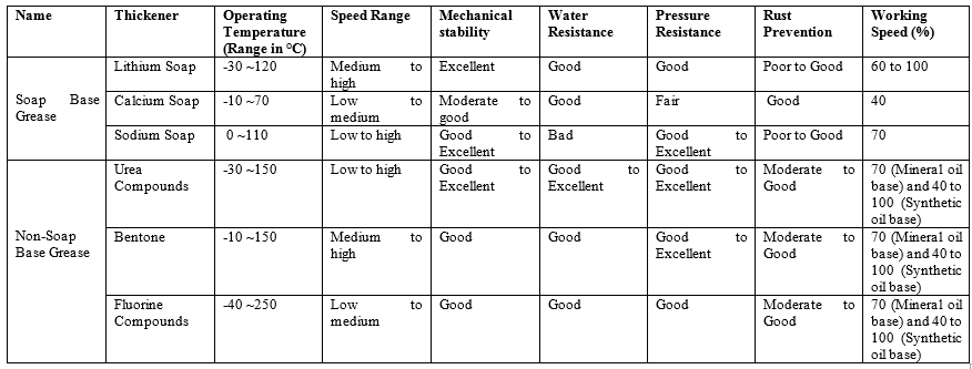
Note: | The limiting speed values listed above are percentage values of the limiting speed given in the bearing manufacturer tables. The grease properties could vary between brands, types and so on. |
Oil Lubrication:
Oil is generally the bearing lubricant of choice on those applications where higher speeds and operating temperatures are expected. When oil is used for bearing lubrication, it should be a high quality, non-oxidizing mineral oil or synthetic oil with similar properties. Some features and advantages of oil lubrication, in addition to the above, are as follows:
■Oil is a better lubricant for high speeds or high temperatures. It can be cooled to help reduce bearing temperature.
■With oil, it is easier to handle and control the amount of lubricant reaching the bearing. It is harder to retain in the bearing. Lubricant losses may be higher than with grease.
■As a liquid, oil can be introduced to the bearing in many ways, such as drip-feed, wick-feed, pressurized circulating systems, oil-bath or air-oil mist. Each is suited to certain types of applications.
■Oil is easier to keep clean for recirculating systems. Oil may be introduced to the bearing housing in many ways.
There are different types of oil lubrication, they are
■Oil bath lubrication
■Drip feed lubrication
■Splash lubrication
■Circulating lubrication
■Jet lubrication
■Oil mist lubrication
■Oil/Air lubricating method
The selection of oil type depends on bearing operating speed, temperature, loading and lubrication method. However, in general, oil with high viscosity should be used for heavier load and high operating temperature. Oil with low viscosity should be used for applications which requires high speed and low temperature. Below table gives you relationship between bearing speed, operating temperature, load and oil viscosity.
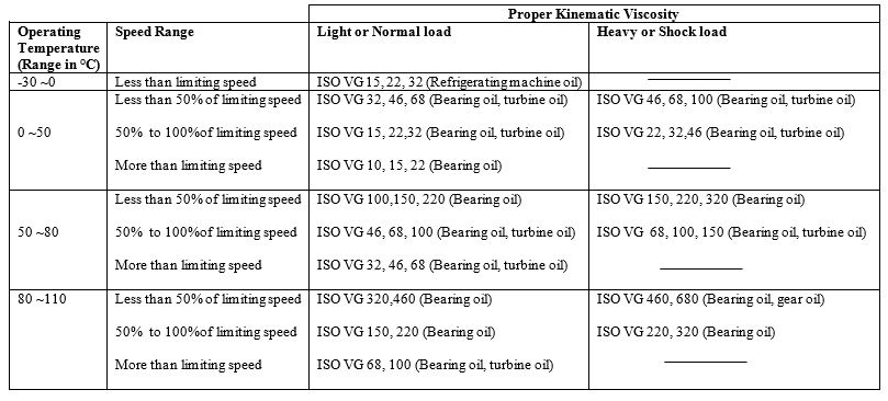
Note: | The limiting speed values listed above are percentage values of the limiting speed given in the bearing manufacturer tables. If the operating temperature is below or above the temperature, it is recommended to consult bearing manufacturer. |
Features of calculation
■Consideration of radial or axial offsets of bearings and diametral/axial clearance.
■Consideration of (nonlinear) bearing stiffness and reaction moment of bearings.
■Resulting axial forces for rolling bearings with pressure angle are calculated automatically.
Background from ISO 281
The calculation of the bearing life time according to ISO 281 is also referred to as L10, catalog or classical method.
The dynamic load rating C is the load, which leads to 10% of failure after 1'000'000 revolutions. The equivalent dynamic bearing load P covers the axial and radial loads of the bearing, together with bearing type related factors. The basic rating life is defined as:
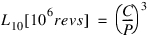 ⇒
⇒
Calculation of service life based on the bearing inner geometry (ISO/TS 16281)
The calculation of the bearing lifetime according to ISO 16281 is also referred to as "reference method" and takes the inner geometry of the bearing into account.
In ISO 16281 the equivalent load is determined via the deflection of the individual rolling parts in contact with inner and outer race (ring). For bearings with cylindrical or tapered rollers the tilting is additionally treated by division of the rolling part into several slices.
The nominal reference lifetime is also calculated based on the ratio of load capacity to effective load, with an expression similar to the previous equation.
The life modification factor for reliability a1 is determined from the failure probability, and it affects the modified lifetime as follows (aISO is determined by various effects like contamination factor, viscosity, lubrication additives, fatigue limit, actual load, bearing type and so on.):
In addition to failure probability, the primary influences on the life calculation per the standard are temperature, speed, load, lubrication and contamination. Note that lubrication may not influence service life if the bearing loads are quite low. The lubrication factor is based on:
■The viscosity of the lubricant at the operating temperature
■A reference viscosity which is based on the bearing geometry and operating speed
The contamination factor is based on:
■The type of lubricant
■Lubricant viscosity at the operating temperature
■Bearing size
■Filtration, which is represented by the impurity factor, Ec, set to 0.5 and not currently editable by Adams Machinery Bearing users.
Note: | If the conditions of the analysis (load and especially speed) are beyond the limits of applicability of the service life estimation standard, then zero is returned for the service life prediction. This is commonly observed when very little load is placed on the bearing. |
Approximation of the inner geometry
As basis, the static and dynamic load rating C0 and C are used, and with formulas from the standards ISO 76 and 281, the following are calculated:
■number/diameter of rolling elements (Z, Dw).
■pitch diameter (Dpw).
■roller length (Lwe, for roller bearings).
■raceway curvatures (when applies).
The approximation of the inner geometry may result in different values than the bearings actually have.
Calculation of bearing loads
■The outer ring is assumed fixed.
■For the inner ring, which is assumed fixed on the corresponding shaft, a translation and rotation of the center is given: posi and roti.
■Each rolling element defines a radial vector r and a normal vector n.
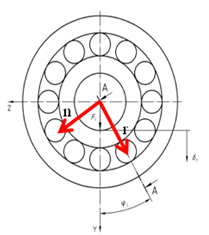
■For the calculation of the loads on a rolling element, only displacements on the local radial plane (defined by vector r and the bearing axis) are considered.
■The distance between the centers of curvature of the races is calculated.
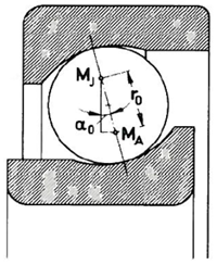
■With a given distance of centers of curvature the deflection is known and the load can be calculated by the contact stiffness.
■For roller bearings the roller is split into 41 sections (requirement by ISO/TS 16281 is ns ≥ 30).
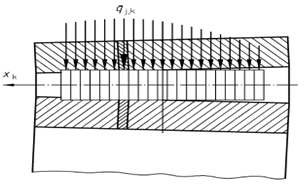
■The roller is considered to be fixed to the inner ring.
■Axial loads for cylindrical bearings are considered according to Harris.
■The stiffness is calculated using differences of deflections and rotations. For higher accuracy symmetric differences around current position are used. The stiffness matrix K is a 5x5 matrix (3 linear and 2 rotational stiffnesses).