Cam Profile Generation 
From this wizard a cam profile can be derived based on a specified desired follower motion.
The Cam Profile geometry can be created from a follower motion and by entering the basic parameters.
The follower motion can input in the following ways:
1. Follower motion created using the follower motion function builder can be selected.
2. Follower motion can be imported from a CSV file. The data in the .csv file can be based on Time or Cam Angle.
Note: | Cam profile generation runs a background simulation to generate the profile via a trace spline; so, an Adams Solver license is briefly consumed during this action. |
Types of Cam Profile
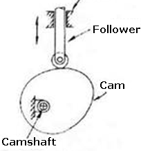
Disk Cam
The most commonly used cam is the disc cam (also known as plate cam or radial cam) which is cut out of a flat plate. Here, the follower moves in a plane perpendicular to the axis of rotation of the camshaft.
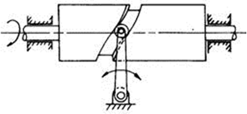
Cylindrical Cam
A cylindrical cam or barrel cam is a cam in which the follower rides on the surface of a cylinder. In the most common type, the follower rides in a groove cut into the surface of a cylinder. These cams are principally used to convert rotational motion to linear motion parallel to the rotational axis of the cylinder. A cylinder may have several grooves cut into the surface and drive several followers. Cylindrical cams can provide motions that involve more than a single rotation of the cylinder.
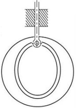
Single sided Grooved Cam
A single sided grooved cam produces motion by using a follower riding on the face of a disk. The most common type has the follower ride in a slot so that the captive follower produces radial motion with positive positioning without the need for a spring or other mechanism to keep the follower in contact with the control surface. A single sided grooved cam of this type generally has only one slot for a follower on each face.
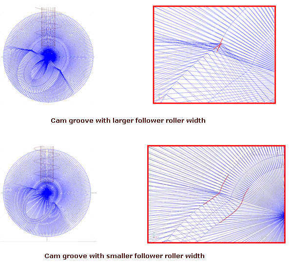
Note: | Some single-sided grooved cam geometry can be problematic. In some circumstances the groove geometry folds onto itself and the groove width is artificially narrowed and/or an unnecessarily sharp edge is introduced. The likelihood of encountering this problem increases as the groove profile curve changes direction more drastically and/or the groove width increases (the figure below shows an example). This problem will not cause any simulation problems when using the constraint representation of the cam-roller interaction. But, when using a 3D contact between the cam and the roller this geometric perturbation can cause a problem in the contact calculation. |
Parameters
Disk Type | Cylindrical Type | Single Sided Groove Type |
|---|---|---|
Minimum Radius | Cam Radius | Cam Radius |
Thickness | Cam Length | Cam Thickness |
Groove Width | Groove Width | |
Groove Depth | Groove Depth |
On entering the follower motion and the above parameters, the profile points of the wire geometry representing the disk Cam edge profile or the groove geometry is displayed and then the Cam profile is generated as a 3D shell geometry.