Cam-Follower System Creation 
From this wizard the cam-follower system is created. The specifics of the configuration and modeling method are inputs and Adams Machinery generates the actual cam and follower parts, constraints, contacts and so on.
The Cam Profile that needs to be part of the Cam-follower system can be inputted in two ways
1. Cam Profile created using the Cam Profile Wizard can be just selected. In this case, the parameters defined during the Cam profile Generation are displayed.
2. A Cam Profile can be imported from a CSV file also. The CSV file needs to contain X,Y & Z data or r,  & Z data of the wire geometry representing the disk Cam edge profile or the groove geometry. The parameters like radius, thickness and Groove parameters are to be entered here.
& Z data of the wire geometry representing the disk Cam edge profile or the groove geometry. The parameters like radius, thickness and Groove parameters are to be entered here.The Cam -follower system may contain 1 or 2 followers of same type positioned radially based on the angular offset desired by the user.
Incase of pivotal follower, the pivot point of the second follower can be picked from the screen.
The Connection between the Cam and the follower can be either
1. Constraint or
2. Contact
Incase of Contact, the Contact parameters that are defined in the create contact dialog box are to be entered.
Types of Followers
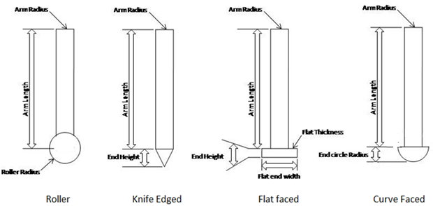
1. Knife-Edge follower
This is the simplest type. If the contacting end of the follower has a sharp knife edge, it is called a knife edge follower. This cam follower mechanism is rarely used because of excessive wear due to small area of contact. In this follower a considerable thrust exists between the follower and guide. When it is adopted, it is usually for reciprocating motion, running in slides and there is considerable side thrust, this being a component of the thrust from the cam.
2. Roller follower
If the contacting end of the follower is a roller, it is called a roller follower. This eliminates the problem of rapid wear since the sliding effect is largely replaced by a roller action. Some sliding will still take place due to the varying peripheral speed of the cam profile, due to the changing radius of the point of contact. Wear rate is greatly reduced because of rolling motion between contacting surfaces. In roller followers also there is side thrust present between follower and the guide. Again, with the roller follower, considerable side thrusts are present, a disadvantage when dealing with reciprocating motions. This side thrust will be increased when using small rollers. Roller followers are commonly used where more space is available such as large stationary gas or oil engines and aircraft engines.
3. Flat-Face follower
If the contacting end of the follower is perfectly flat faced, it is called a flat faced follower. The thrust at the bearing exerted is less as compared to other followers. The only side thrust is due to friction between the contact surfaces of the follower and the cam. The problem of wear is not so great as with the knife-edge follower, since the point of contact between the cam and follower will move across the face of the follower according to the change of shape of the cam. The thrust can be further reduced by properly offsetting the follower from the axis of rotation of cam so that when the cam rotates, the follower also rotates about its axis. Thus the contact with the cam will tend to cause rotation of the follower. The cam profile, to work with a flatfoot follower, must be convex at all parts, in order to prevent the corners of the follower digging into the cam profile. The minimum cam radius should be as small as possible to minimize sliding velocity and friction. These are commonly used in automobiles.
4. Curve Faced or Mushroom follower
If the contacting end of the follower is of spherical shape, it is called a spherical faced follower. In flat faced follower's high surface stress are produced. To minimize these stresses the follower is machined to spherical shape.
The cam and follower can be separately attached to the ground, rigid part or flexible part through joints or bushings. The type of joints, bushing parameters and the connection part can be inputted.
The follower can be loaded using a spring if required. The parameters like stiffness, damping co-efficient and preload can be defined.
Follower Tilt Angle
In order to facilitate assembly constraints, the follower can be tilted from the Cam Y-axis within the range +45 deg to -45 deg. This option is applicable only to Translation Motion type of Disk and Single sided Grooved Cam. In two-follower systems, this tilt value will be applied to both followers.
Note: | When the follower is tilted, the motion observed by the follower varies from the follower motion defined during Cam Creation. |
The material properties of the Cam and each follower can be defined by:
1. User Input
2. Geometry & Density
3. Geometry & Material Properties
The cam-follower system will contain the following set of automatically created output requests described below:
Cam profile request
The request created under the cam profile has the following components:
Angular displacement
This request provides how much angle has the cam rotated with respect to the independent axis.
Angular velocity
This request provides how much angular velocity has it attained with respect to the independent axis.
Angular acceleration
This request provides how much angular acceleration has it attained with respect to the independent axis.
Follower request
Follower request further contains two more requests:
Follower output
1. Translational displacement
This request provides how much length has the cam translated with respect to the independent axis.
2. Translational velocity
This request provides how much translational velocity has it attained with respect to the independent axis.
3. Translational acceleration
This request provides how much translational acceleration has it attained with respect to the independent axis.
Note that the above components appear if the follower is of translational type. If the follower is of pivotal type the components are changed to angular displacement, angular velocity and angular acceleration respectively.
Pressure Angle
Pressure angle request
The request provides the measurement for pressure angle in cam- follower arrangement.