Chain
In Adams Machinery, you can work with linear, nonlinear and advanced chains. A chain can be:
■elastic (model type = 2D Links, 3D Links, 3D Links Non Planar) - Contains chain link parts and their connections. The chain also contains the contact forces between sprockets, guides, and chain link parts.
■rigid (model type = Constrained) - Contains parts, couplers, and a simple geometry. Each coupler constrains the rotational displacement of two sprockets.
You wrap the chain around anchors, sprockets and guides. The Wrapping order of sprocket should always be in clockwise direction. The chain always references a linear or nonlinear chain component. The links are connected as follows:
■Linear chains - Bushings
■Nonlinear and advanced chains - Fields
The Chain system consist of Roller Sprocket/Chain and Silent Sprocket/Silent Chain.
Roller Sprocket/Chain
Sprocket
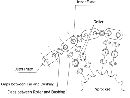
The roller chain system employs a chain composed of cylindrical rollers connected to each other by links on each side. The chain mates with toothed sprockets.
Chain
It consists of a pair of inner and outer links, which are held together using a set of rollers. Each link rotates independently around the rollers. The teeth on the roller sprocket fit into the space between each link, or into the link itself. As the sprocket rotates, it transfers this rotational energy to the chain.
Methods
The following methods available in the Roller Sprocket type.
1. Constrained
This is a simple method used to transmit the velocity through a ratio. This method is used when forces and components involved are neglected and only speed reduction or multiplication is of interest.
2. 2D Links
The chain is modeled with planar part links connected to each other with stiffness elements and analytically calculates the contact forces between the links, sprockets and guides. The modeling method is faster to simulate than 3D links but the axis of rotation must be parallel to one of the global axes.
3. 3D Links
The chain is modeled with 3D part links connected to each other with stiffness elements and analytically calculates the contact forces between the links and sprockets and guides. Use this method when the axis of rotation is not parallel to one of the global axes.
4. 3D Links Non Planar
The chain is modeled with 3D part links connected to each other with stiffness elements and analytically calculated contact forces between the links and sprockets and guides. The chain can move laterally across the sprockets and accommodate small amounts of out of plane offset and misalignment in the sprockets.
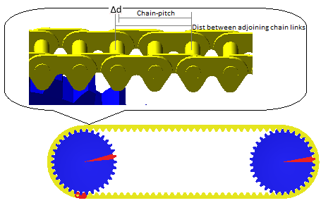
Tension warning while wrapping Chain
Total length of chain perimeter over all sprockets may not be exactly equally to (number of chain-links x chain-pitch). The perimeter is calculated at pitch circle diameter based on center location and diameter of sprockets specified by user. Chain-pitch is specified by user. If chain perimeter is not exact multiple of chain-pitch then it will result in overlap/slackness between two adjoining chain-links resulting in negative/positive tension as below:
For Silent Chain:
■Tension = Δd × Chain Translational Stiffness (KX)
For Roller Chain - Linear:
■Tension = Δd × Chain Translational Stiffness(KX)
For Roller Chain - Non-Linear:
■Tension = K1 x Δd + K2 x Δd3 + K3 x Δd5
For Roller Chain - Advanced:
■Tension = K1 x Δd + K2 x Δd2 + K3 x Δd3 + K4 x Δd4 + K5 x Δd5
where:
■Δd = (Distance between adjoining chain-links - Chain_pitch)
Silent Sprocket/Silent Chain
Sprocket
The silent chain system, also known as an involute chain, employs a chain composed of cylindrical rollers connected to each other by links on each side which have a toothed profile. The chain mates with toothed sprockets. Silent Sprockets are not applicable for Open loop chain configuration.
Chain
It consists of plates and pins. The link plates of the Silent Chain strike the sprocket at an angle, the impact and the noise are reduced. This is why these chains are called "silent."
The silent chain element is an array referenced by involute sprockets. It contains all chain parameters. All sprockets that will be in contact with a specific chain must reference the same chain properties element associated with the chain.
Chain Links
The chain links element contains link parts and their connections. You can wrap the chain around sprockets and guides. The chain also contains the contact forces between the chain link parts and the sprockets and guides.
There are no predefined results for the chain properties element or the chain links element.
Silent Chain Link Specification
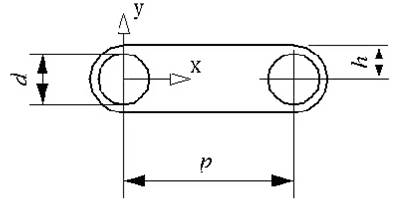
The shape of a silent chain link is described by sections of arcs and lines going around two reference points. The left half refers to the left reference point, and the right half refers to the right reference point.
Chain Link Geometry (the part is positioned at the left reference)
Note that the Left Reference is also the part reference, which is the reference for mass and inertia.
The shape is defined by means of arcs and points. Arcs are defined by giving the x-y coordinates and the radius. Points are defined by x-y coordinates and a radius of 0.
The resulting shape will then be a mixture of arcs and straight lines. If, for example, two arcs are defined with a distance between them, there will be a straight line between them, which will be tangent to both arcs. Between an arc and a point, a straight line will be drawn which is tangent to the arc and ends in the point. This way points can be used to introduce edges on the link.
The definition of both halves of the link shape (left and right) will start from the valley between the teeth. So the left half is defined clockwise and the right half is defined counterclockwise. The first entry can be either a point or an arc. Between the start entries for the two halves, a straight line will be drawn according to the above stated rules. The same applies between the two end entries. The first arc (or the second if the first is a point) of each circumference half will be regarded as having its center point outside the circumference (concave). All other arc entries will have their centers inside the circumference (convex).
The chain link in the figure above is defined using the following arcs and points:
Left X | Left Y | Left R | Right X | Right Y | Right R |
|---|---|---|---|---|---|
3.0 | -2.5 | -1.5 | -3.0 | -2.5 | -1.5 |
-1.1 | -2.5 | 2.5 | 1.1 | -2.5 | 2.5 |
0.15 | -4.6651 | 0.0 | -0.15 | -4.6651 | 0.0 |
-2.0 | 0.0 | 0.0 | 2.0 | 0.0 | 0.0 |
0.0 | 0.0 | 2.0 | 0.0 | 0.0 | 2.0 |
Methods
The following methods available in the Silent Sprocket type.
1. Constrained
This is a simple method used to transmit the velocity through a ratio. This method is used when forces and components involved are neglected and only speed reduction or multiplication is of interest.
2. 2D Links
The chain is constrained to a plane. The chain is modeled with planar part links connected to each other with stiffness elements and analytically calculated contact forces between the links, sprockets and guides. This modeling method is faster to simulate than 3D links but the axis of rotation must be parallel to one of the global axis.
3. 3D Links
The chain is constrained to a plane. The chain is modeled with 3D part links connected each other with stiffness elements and analytically calculated contact forces between the links and sprockets and guides. Use this method when the axis of rotation is not parallel to one of the global axes.
Chain Link Geometry
The part's center of gravity is positioned in the center of the first roller.
Chain (linear, nonlinear and Advanced)
A chain is an array referenced by sprockets. It contains all chain parameters. To create the Chain links, you must wrap the chain. All sprockets that will be in contact with a specific chain must reference the same chain component associated with the chain.
There are no predefined results for the chain or the chain links components.
Linear Chain Connection Parameters
The following parameters specify a function for the translational stiffness of the link connections:
■TS - Translational stiffness (x direction)
■TD - Translational damping (x direction)
■RD - Rotational damping (z direction)
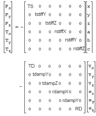
Stiffness and Damping Matrices
When calculating the stiffness and damping matrices, Adams Machinery uses the following predefined values:
■translational stiffness of chain connection, tstiff_x = 1.0E+05 N/mm
■translational stiffness of chain connection, tstiff_y = 1.0E+05 N/mm
■translational stiffness of chain connection, tstiff_z = 1.0E+05 N/mm
■translational damping of chain connection, tdamp_x = 1000.0 N-ms/mm
■translational damping of chain connection, tdamp_y = 1000.0 N-ms/mm
■translational damping of chain connection, tdamp_z = 1000.0 N-ms/mm
■rotational stiffness of chain connection, rstiff_x = 1.0E+04 N-mm/deg
■rotational stiffness of chain connection, rstiff_y = 1.0E+04 N-mm/deg
■rotational stiffness of chain connection, rstiff_z = 0.0
■rotational damping of chain connection, rdamp_x = 100 N-mm-ms/deg
■rotational damping of chain connection, rdamp_y = 100 N-mm-ms/deg
■rotational damping of chain connection, rdamp_z = 0.0
For information on the BUSHING statement, see the Adams Solver online help.
Nonlinear Chain Connection Parameters
The following parameters specify a function for the translational stiffness of the link connections:
TD - Translational damping (x direction)
RD - Rotational damping (z direction
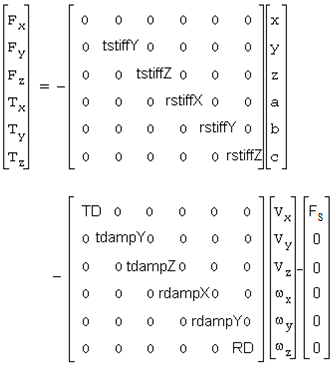
Stiffness and Damping Matrices
The following equation yields the nonlinear stiffness term of the translational force of the link connections:
Fs = K1*dx + K2*dx3+ K3*dx5
When calculating the stiffness and damping matrices, Adams Machinery uses the following predefined values:
■translational stiffness of chain connection, tstiff_x1 = 6.8E+04 N/mm
■translational stiffness of chain connection, tstiff_x2 = 0.0 N/mm
■translational stiffness of chain connection, tstiff_x3 = 6.8E+04 N/mm
■translational damping of chain link connection tdamp_link = 600.0 N-ms/mm
■translational stiffness of chain connection, tstiff_y = 6.8E+04 N/mm
■translational stiffness of chain connection, tstiff_z = 6.8E+04 N/mm
■translational damping of chain connection, tdamp_y = 100.0 N-ms/mm
■translational damping of chain connection, tdamp_z = 100.0 N-ms/mm
■rotational stiffness of chain connection, rstiff_x = 6.8E+04 N-mm/deg
■rotational stiffness of chain connection, rstiff_y = 6.8E+04 N-mm/deg
■rotational stiffness of chain connection, rstiff_z = 0.0
■rotational damping of chain connection, rdamp_x = 100.0 N-mm-ms/deg
■rotational damping of chain connection, rdamp_y = 100.0 N-mm-ms/deg
■rotational damping of chain connection, rdamp_z = 100.0 N-mm-ms/deg
Advanced Chain Connection Parameters
The following equation yields the advanced stiffness term of the translational force of the link connections:
Fx=K1*dx+K2*dx^2+k3*dx^3+k4*dx^4+k5*dx^5+c*vr
Where:
■dx is the displacement of the center of the inner circle relative to the center of the outer circle.
■vr is the radial velocity between the centers
■k1 - k5 are stiffness coefficients
■c is the damping coefficient
The gap length is gap between Pin/Roller and Bushing. It is defined as the length g on the figure below:
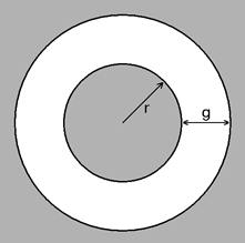
Where:
■r is the inner radius
■g is the gap size
For information on the field statement, see the Adams Solver online help.
When calculating the stiffness and damping matrices, Adams Machinery uses the following predefined values:
Link Stiffness
■translational stiffness of chain link connection tstiff_link_1= 6.8E+04 N/mm
■translational stiffness of chain link connection tstiff_link_2= 0.0
■translational stiffness of chain link connection tstiff_link_3= 6.8E+04 N/mm
■translational stiffness of chain link connection tstiff_link_4= 0.0
■translational stiffness of chain link connection tstiff_link_5= 6.8E+04 N/mm
■translational damping of chain link connection tdamp_link = 600.0 N-ms/mm
■rotational stiffness of chain link connection rstiff_link_x = 1.745329E+04 N-mm/deg
■rotational stiffness of chain link connection rstiff_link_y = 1.745329E+04 N-mm/deg
■rotational stiffness of chain link connection rstiff_link_z = 0.0
■rotational damping of chain link connection rdamp_link_x = 174.5329 N-mm-ms/deg
■rotational damping of chain link connection rdamp_link_y = 174.5329 N-mm-ms/deg
■rotational damping of chain link connection rdamp_link_z = 100 N-mm-ms/deg
■translational stiffness of chain link connection tstiff_link_x1= 6.8E+04
■translational stiffness of chain link connection tstiff_link_z = 2.0E+05
■translational damping of chain link connection tdamp_link = 600.0
■translational damping of chain link connection tdamp_link_z = 600.0
Roller Stiffness
■translational stiffness of chain roller connection tstiff_roller_1= 6.8E+04 N/mm
■translational stiffness of chain roller connection tstiff_roller_2= 0.0
■translational stiffness of chain roller connection tstiff_roller_3= 6.8E+04 N/mm
■translational stiffness of chain roller connection tstiff_roller_4= 0.0
■translational stiffness of chain roller connection tstiff_roller_5= 6.8E+04 N/mm
■translational damping of chain roller connection tdamp_roller = 600.0 N-ms/mm
■rotational stiffness of chain roller connection rstiff_roller_x = 1.745329E+04 N-mm/deg
■rotational stiffness of chain roller connection rstiff_roller_y = 1.745329E+04 N-mm/deg
■rotational stiffness of chain roller connection rstiff_roller_z = 0.0
■rotational damping of chain roller connection rdamp_roller_x = 174.5329 N-mm-ms/deg
■rotational damping of chain roller connection rdamp_roller_y = 174.5329 N-mm-ms/deg
■rotational damping of chain roller connection rdamp_roller_z = 100 N-mm-ms/deg
■translational stiffness of chain roller connection tstiff_roller_z = 2.0E+05 N/mm
■translational damping of chain roller connection tdamp_roller_z = 200 N-ms/mm
Notes: | ■To access a listing of the chain properties: ■From the chain object within the model browser or graphics window right-click and select "Info". ■From the Information window click the "properties" object and Apply. 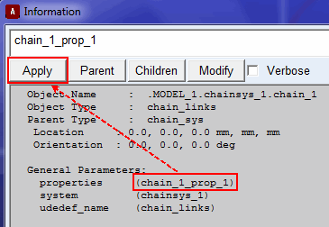 |