Create / Modify Ball Bearing element
Machinery → Bearing AT → Ball Bearing → Element → New/Modify
The dialog box allows you to create Adams View ball bearing element. The bearing geometrical parameters are displayed in the Bearing Specifications part of the dialog box.
Main
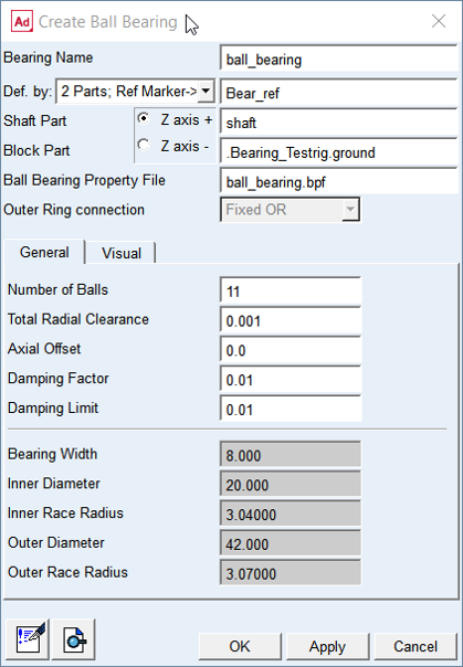
Figure 12 Ball bearing element dialog box - General tab
For the options | Do the following |
|---|---|
Bearing Name | Enter the name of the bearing. |
Def. by. | Select the method of bearing element creation ■2 Parts; Ref Marker -> Select the reference marker to locate and orient new bearing element on any part; select shaft part and block part to attached new bearing element ■2 Markers -> Select markers on shaft part and block part to locate and orient new bearing element Note: Z-axis of reference marker defines rotational axis of bearing element. |
For the 2 Parts; Ref. Marker option you need to specify the Shaft Part and Block Part and one Reference marker to define unique location. | |
Ref. Marker | Select the bearing reference marker to define unique location and orientation of the bearing element. Note: The orientation of the Z axis can be flipped by the "Z axis +" / "Z axis -" radio button. |
Shaft Part | Select the shaft part in your model to attach the bearing inner ring to. The marker will be automatically created on the selected part. |
Block Part | Select the block part in your model to attach the bearing outer ring to. The marker will be automatically created on the selected part. |
For the 2 Markers option you need to specify the Shaft Marker and Block Marker on respective parts to define both, the connectivity and location / orientation of the bearing element. Note: With this option you effectively define initial displacement of bearing rings relative to each other. | |
Shaft Marker | Select a marker on the shaft part in your model to attach the bearing inner ring to. |
Block Marker | Select a marker on the block part in your model to attach the bearing outer ring to. This is reference marker of bearing. |
Ball Bearing Property File | Specify the ball bearing property file (*.bpf) |
Outer Ring connection | ■Fixed OR-> Select to fix outer ring to block part ■Floating Ring-> Select to release axial and radial DoF of outer ring ■Axial Spring-> Select to create axial spring element to force preload of outer ring relative to block part |
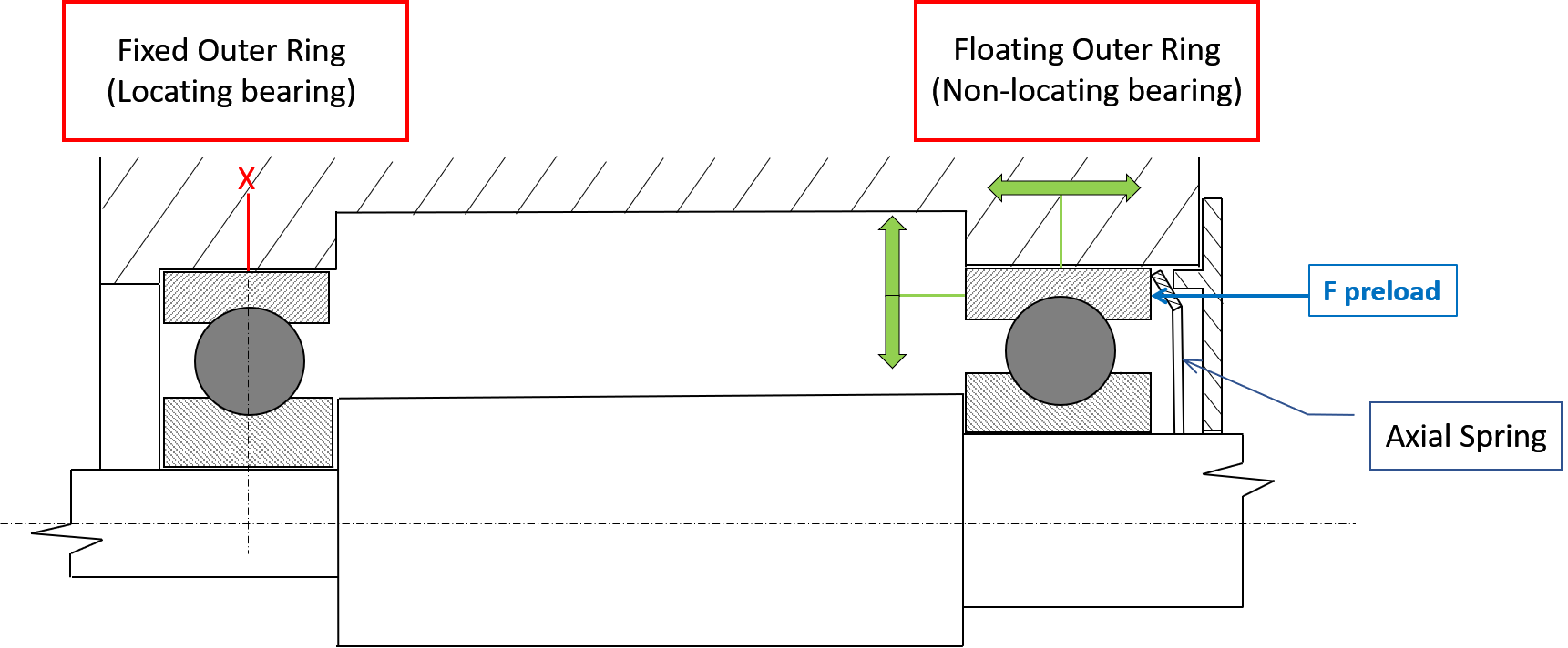
Figure 13 Fixed OR vs. Floating ring with Axial Spring
General
For the options | Do the following |
|---|---|
Number of Balls | You can adjust the value of input for the preprocessing phase for Adams simulation. Default value as specified in the *.bpf property file; a maximum of 150 balls is supported. |
Total Radial Clearance | It is radial operating clearance determined on a fitted bearing still warm from operation. It is defined as the amount by which the inner ring can be moved in a radial direction from one extreme position to the other in relation to the outer ring (see Figure 14). The total radial clearance can be positive or negative. In case of negative clearance, the rolling elements are already preloaded at the design position. Default value is taken from *.bpf property file. |
Axial Offset | Enter axial offset A positive axial offset means that the marker of the shaft is translated in positive direction along the Z-axis of the bearing. The first option for pre-loading and clearance free mounting is the application of a negative clearance. The second option is given by the application of a negative offset. Default = 0.0 |
Damping Factor | Damping force is applied per roller, when the compression of the roller is increasing. The damping force is defined by following equation Damping_force = roller_load * (tran_velocity * damping factor) |
Damping Limit | If the expression (tran_velocity * damping factor) exceeds the Damping Limit, then the damping force is becoming: Damping_force = roller_load * damping limit Be aware that very high damping can slow down the integrator. The Damping Limit was introduced to prevent unintentional high damping. |
Figure 14 Total Radial Clearance
Visual
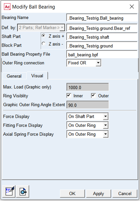
Figure 15 Ball bearing element dialog box - Visual tab
For the options | Do the following |
|---|---|
Max.Load (Graphic Only) | This parameter is used for animations only, when color for the balls indicate the level of loading. This color code (refer Figure 16) is activated, when you set the toggle on under Bearing AT -> Animation Settings. |
Ring Visibility | Toggle ON or OFF to put the Inner and Outer ring visible or invisible state |
Graphic Outer Ring Angle Extent | Adjust this parameter to take a look into the bearing (Figure 17). A portion of the outer ring from this input till 360 degrees is not displayed. |
Force Display | Set to whether you want to display force graphics for shaft part or none. |
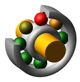
Figure 16 Color code for animation
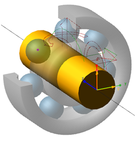
Figure 17 Graphics outer ring extend
Floating outer ring
Floating outer ring feature allows modeling of deep groove ball bearing as non-locating bearing. User can define parameters of viscous damping and Coulomb friction along axial direction in corresponding tabs of dialog box. One can also define loose fit between outer ring and housing seat.
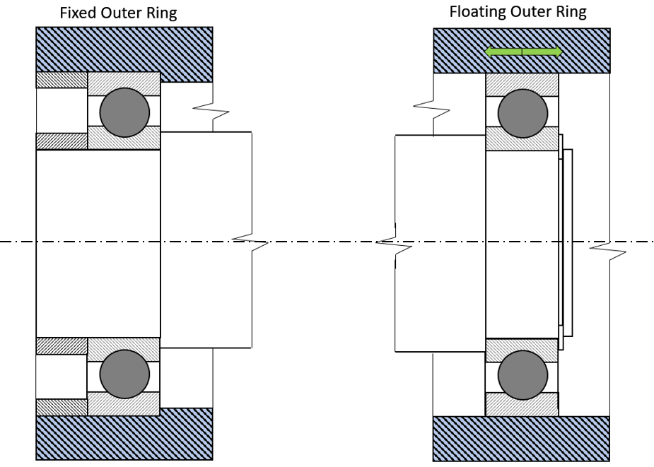
Figure 18 Fixed outer ring vs. floating outer ring
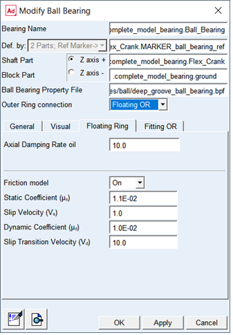
Figure 19 Element dialog box - Floating Outer Ring tab
For the options | Do the following |
|---|---|
Axial Damping Rate oil | Enter value of Axial Damping Rate Oil to define hydrodynamic damping as a function of oil squeeze velocity. Fhyd = damp rate oil * squeeze vel Default: 10.0 |
Friction model | Choose one of the following options: ■Off - no friction force is computed. In this case the other fields in this card will be disabled ■On - friction force is computed ■Default: Off |
Static Coefficient (µs) | Enter value of Static Friction Coefficient to define Coulomb friction Default: 1.1e-2 [-] |
Slip Velocity (vs) | Enter value of Slip Velocity to define Coulomb friction Default: 1.0 [mm/sec] |
Dynamic Coefficient (µd) | Enter value of Dynamic Coefficient to define Coulomb friction Default: 1.0e-2 [-] |
Transition Velocity Slip (vd) | Enter value of Transition Velocity Slip to define Coulomb friction Default: 10.0 [mm/sec] |
The static friction coefficient is usually somewhat higher than the dynamic friction coefficient. Step functions are used for smoothing the transitions (see Figure 20). Parameter of slip velocity limits the region of sign change of the sliding velocity. The combination of very small slip velocity and high friction can reduce the performance of the integrator. Transition velocity defines the start of the region, where the dynamic friction is constant. A small difference between slip velocity and transition velocity could also lead to numerical issues of the integrator.
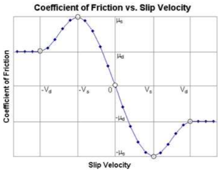
Figure 20 Friction coefficient
Axial Spring
Axial spring is always used with floating outer ring to apply axial preload and eliminate axial clearance.
It serves to define the clearance and create a preload in the axial direction. It is also used to compensate for thermal expansion of the shaft mounting in housing.
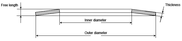
Figure 21 Axial Spring
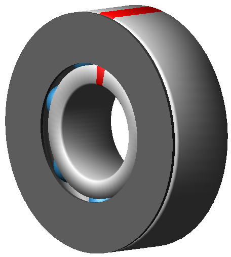
Figure 22 Axial spring in Adams view
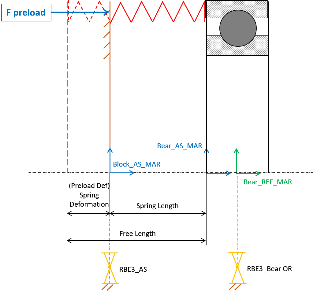
Figure 23 Axial Spring diagram
Axial Spring is defined with the required parameters, which can be modified at any time in the corresponding tab of element dialog box (see Figure 24).
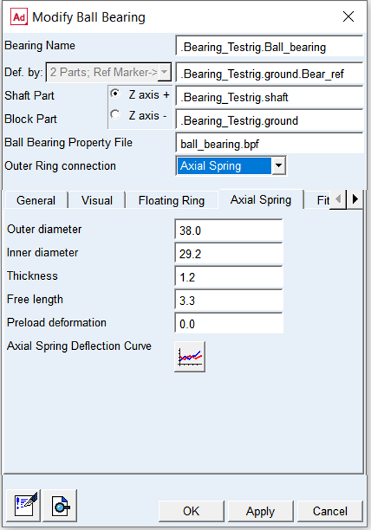
Figure 24 Element dialog box - Axial Spring tab
For the options | Do the following |
|---|---|
Outer diameter | For this parameter use a value close to the outer diameter of bearing for which is axial spring created |
Inner diameter | For this parameter use a value not less than the inner diameter of bearing for which is axial spring created |
Thickness | Use required value of thickness of the axial spring (see Figure 21) |
Free length | Use required value of free length of axial spring (see Figure 21) |
Preload deformation | Deformation at required axial preload force |
Axial spring deflection curve | Represents the stiffness characteristic of the axial spring. See Figure 25. |
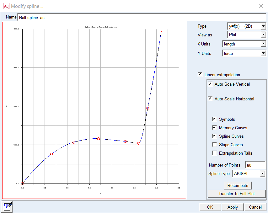
Figure 25 Define Spring force - deflection curve
Fitting ring
One can convert locating bearing such as deep groove ball bearing into non-locating bearing by introducing floating outer ring. Simplified modeling allows axial motion of outer ring relative to housing bore by applying Radial Lock. In case user requires more detailed modeling one can define radial clearance between outer ring and housing bore (Block Part) as well as stiffness and damping parameters. Current implementation does not allow bending (tilting) of outer ring relative to housing bore.
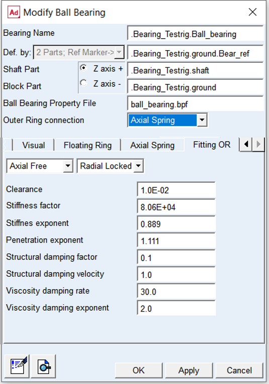
Figure 26 Element dialog box - Fitting outer ring tab
For the options | Do the following |
|---|---|
Axial Free/Locked | Select to release or fix axial degrees of freedom in translational direction (Tra_Z) of outer ring relative to block part |
Radial Free/Locked | Select to release or fix radial degrees of freedom in translational direction (Tra_X, Tra_Y) of outer ring relative to block part |
Clearance | Use required value of clearance Default: 1.0e-02 [mm] |
Stiffness factor | Use required value of stiffness factor Default: 8.06e+04 [N/mm] |
Stiffness exponent | Use required value of stiffness exponent: Default: 8 / 9 = 0.889 |
Penetration exponent | Use required value of penetration exponent: Default: 10 / 9 = 1.111 |
Structural damping factor | Use required value of structural damping factor to define structural damping. It represents material damping therefore it is made proportional to the contact force Default: 0.1 |
Structural damping velocity | Use required value of structural damping velocity Default: 1.0 |
Viscosity damping rate | Use required value of viscosity damping rate to define hydrodynamic damping as a function of oil squeeze velocity and actual oil film gap Default: 30.0 |
Viscosity damping exponent | Use value of viscosity damping exponent Default: 2.0 |
Extended definition:
Figure 27 Outer ring fitting clearance
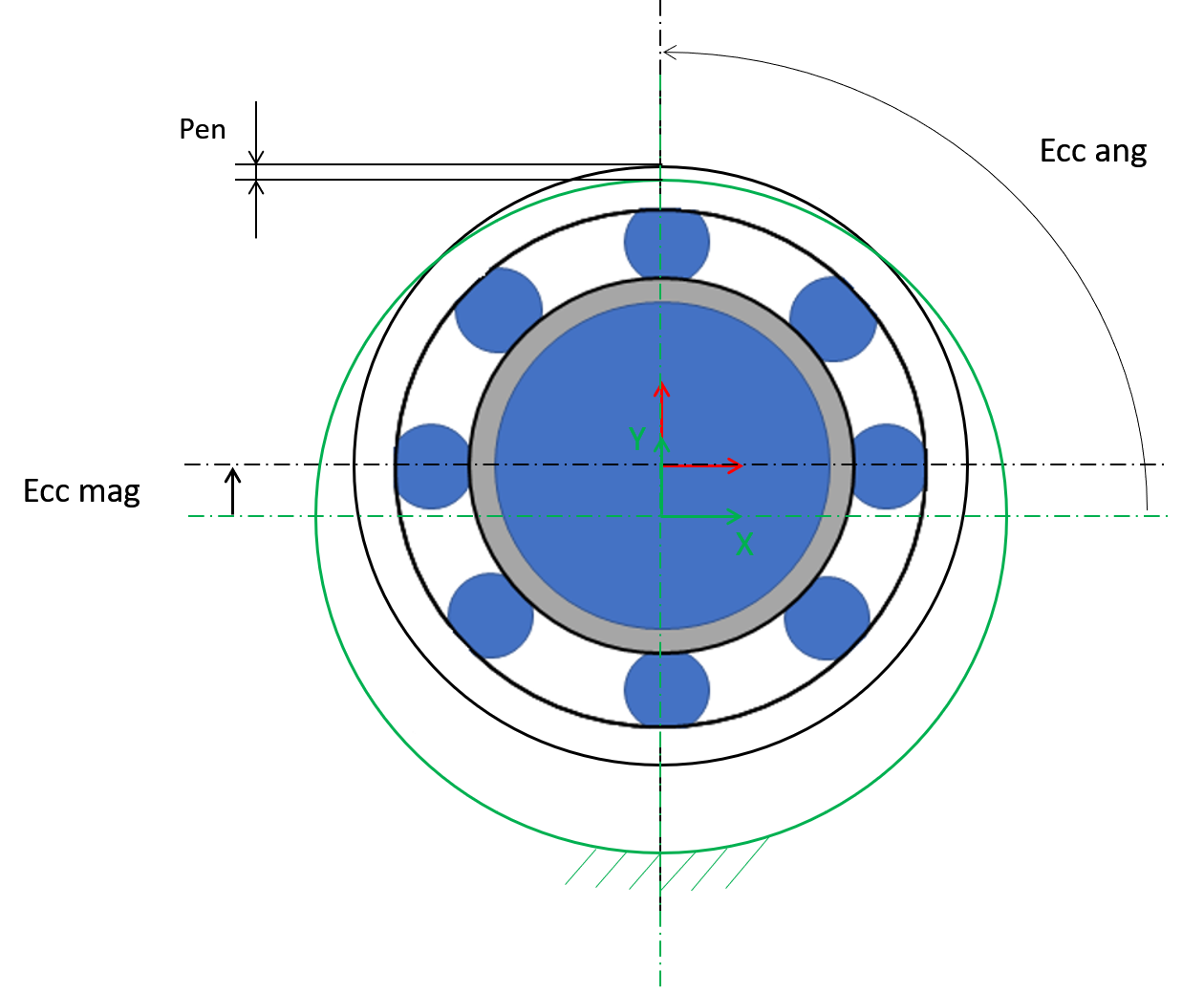
Figure 28 Outer ring housing contact
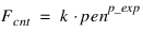 | (1) |
where:
■pen - penetration of outer ring to housing
■p_exp - penetration exponent
■k - contact stiffness
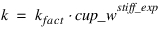 | (2) |
where:
■k_fact - stiffness factor
■cup_w - width of outer ring
■stiff_exp - stiffness exponent
 | (3) |
There is no hydrodynamic damping, when b < 0; see Equation (4)
 | (4) |
Hydrodynamic damping increases exponentially with decreasing oil film height. The introduction of the damping exponent dexp in Equation (5) is used for this purpose; see Figure 29.
 | (5) |
In case of contact (penetration), the hydrodynamic damping force is set as shown by Equation (6).
 | (6) |
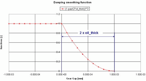
Figure 29 Function of hydrodynamic damping
Structural damping is usually a small value. The structural damping force is made proportional to the contact force as shown by Equation (7). A value of 0.01 means that the structural damping force is 1.0 percent of the elastic contact force.
 | (7) |