Create Belt - Trapezoidal Toothed
Machinery → Create Belt
For the option | Do the following |
|---|---|
Belt Name | Enter the belt name. |
Axis of Rotation | Axis of Rotation can be one of the following: ■Orientation ■Pick (Marker) ■Global Z ■Global X ■Global Y |
Reference Location | Enter the value for reference location. |
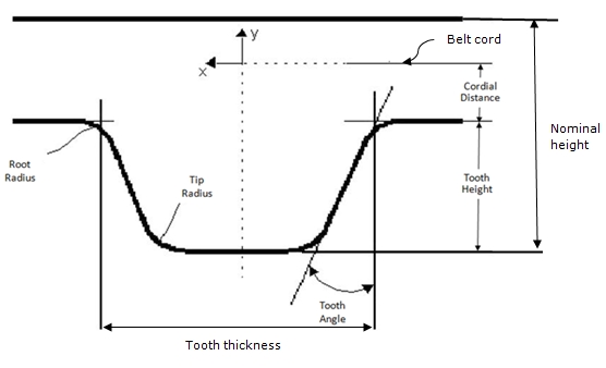
Geometry As you specify the following parameters, you might find it useful to reference Belt Profile According to ISO 5296. | |
Belt pitch | Enter the distance between the centerlines of two belt teeth. |
Belt width | Enter the width of the belt. |
Nominal height | Enter the nominal height, which is the distance between tooth tip and outer belt surface. |
Cordial distance | Enter the distance between the tooth root and the belt cord. |
Teeth number | You can either: ■Select it - Enter the total number of teeth of the belt. ■Clear its selection - Adams Machinery calculates the number of teeth needed based on belt pitch and the path length. |
Tooth height | Enter the tooth height. The tooth height is the distance between the tooth root and tooth tip. |
Tooth thickness | Enter the thickness of the tooth at the root. |
Tooth angle | Enter the tooth angle. |
Tooth tip radius | Enter the tooth tip radius. |
Tooth root radius | Enter the tooth root radius. |
Belt stiffness | |
Stiffness | ■Geometry & Material ■User entered |
If you set Section Connections to Geometry & Material, Adams Machinery displays the following options. Learn how Adams Machinery uses the following options to calculate stiffness parameters. | |
land section area | Enter the cross-section area of the land section. |
land section Inertia | Enter the area moment of inertia of the land-section cross section, about the neutral axis (z-z). It is expressed as unit length to the fourth power. It is sometimes referred to as the second moment of area about the z-axis. The z-axis is along the width of the belt. For a solid rectangular section: I = Izz = width * height3/12 where the height of the land-section cross section is (Nominal Height - Tooth Height). |
Young’s modulus | Enter the value of the belt material. |
Damping Ratio | Enter the damping ratio. The damping ratio is in time units. |
If you select User entered, the following options available: | |
K axial | Enter the axial stiffness. The stiffness is in force units / length units. |
K transverse | Enter the transverse stiffness. The stiffness is in force units / length units. |
K torsional | Enter the torsional stiffness. The stiffness is in force units * length units / angle units. |
K coupling | Enter the coupling stiffness. The stiffness is in force units. |
C axial | Enter the axial damping. The damping is in force units * time units / length units. |
C transverse | Enter the transverse damping. The damping is in force units * time units / length units. |
C torsional | Enter the torsional damping. The damping is in force units * length units * time units / angle units. |
Geometry settings | Belt Graphics ■Standard A simplified belt graphic in the shape of a rectangular prism. Animations may perform faster with this option. ■Shell Fully detailed belt graphic which captures the grooves or teeth of the belt. Force Graphics ■Enable Force graphic vectors will be displayed while animating results. ■Disable Force graphic vectors will not be displayed while animating results. |