Create Belt - Smooth 2D and 3D Links
Machinery → Create Belt
For the option | Do the following |
|---|---|
Belt Name | Enter the belt name. |
Axis of Rotation | Axis of Rotation can be one of the following: ■Orientation ■Pick (Marker) ■Global Z ■Global X ■Global Y |
Reference Location | Enter the value for reference location. |
Geometry 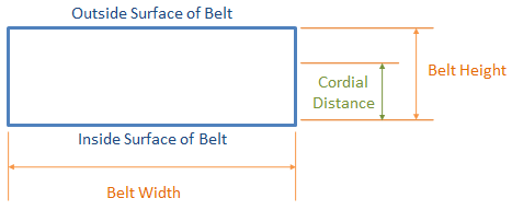 | |
Total Segments | Optionally enter the total number of segments into which the belt is to be discretized. Use this parameter along with the segment length parameter when the total length of the belt is known and Adams will route a belt of this length through the pulley set and report the resulting tension required to do so. |
Segment Length | Enter the length of the individual discrete segments into which the belt model is discretized. Using this parameter in conjunction with "Total Segments" the total length of the belt can be provided as an input (see above). If "Total Segments" is not specified, then Adams will model the belt with the greatest number of segments of this length that still provides some tension (that is, greater than zero belt tension in the design position of the model). |
Belt Height | Enter the total height of the belt. It is also known as "Nominal Height". |
Belt Width | Enter the width of the belt. |
Cordial Distance | Enter the distance from the inner belt surface to the cord inside the belt. |
Belt stiffness | |
Stiffness | ■Geometry & Material ■User entered |
If you set Section Connections to Geometry & Material, Adams Machinery displays the following options. Learn how Adams Machinery uses the following options to calculate stiffness parameters. | |
Segment Area | Enter the cross-sectional area of the segment. |
Section Inertia | Enter the area moment of inertia of the segment cross section, about the neutral axis (z-z). It is expressed as unit length to the fourth power. It is sometimes referred to as the second moment of area about the z-axis. The z-axis is along the width of the belt. For a solid rectangular section: I = Izz = width * height3/12 where the height of the land-section cross section is (Nominal Height - Tooth Height). |
Young’s Modulus | Enter the Young's modulus of the belt material. |
Damping Ratio | Enter the damping ratio (damping coefficient). |
If you select User entered, Adams Machinery displays the following options. Learn how Adams Machinery uses the following options to calculate stiffness parameters. | |
K axial | Enter the axial stiffness. The stiffness is in force units / length units. |
C axial | Enter the axial damping. The damping is in force units * time units / length units. |
K transverse | Enter the transverse stiffness. The stiffness is in force units / length units |
C transverse | Enter the transverse damping. The damping is in force units * time units / length units. |
K torsional | Enter the torsional stiffness. The stiffness is in force units * length units / angle units. |
C torsional | Enter the torsional damping. The damping is in force units * length units * time units / angle units. |
K coupling | Enter the coupling stiffness. The stiffness is in force units. |
Geometry settings | Belt Graphics ■Standard A simplified belt graphic in the shape of a rectangular prism. Animations may perform faster with this option. ■Shell Fully detailed belt graphic which captures the grooves or teeth of the belt. Force Graphics ■Enable Force graphic vectors will be displayed while animating results. ■Disable Force graphic vectors will not be displayed while animating results. |