Emag AT Electro Motor Definition
Emag AT Motor Definition allows you to create a file that defines an Electric Motor (both Electromagnetic excitation and Rotor and Stator structures). You can define an Electromagnetic excitation by referencing pre-calculated magnetic field data from 3rd party software. The structures are defined by FE Nastran models for Rotor and Stator. Figure 6 shows how to access the tools you need to define your electric motor.
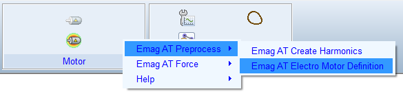
Figure 6 Access to the Gear AT Shape Definition
The Emag AT Electric Motor Definition has the following tabs to help you design an electromotor.
Main
For the options | Do the following |
|---|---|
Mode (Create, Edit) | In Create mode the user can enter manually all parameters to input fields. Edit mode enables editing of existing property file (EMP). In addition, individual preprocessing steps can be executed so only part of data stored in existing emf file can be processed resp. exchanged. |
Property file (EMP) | This file stores all essential motor parameters, general parameters, references for excitation force input data, references for structure definition of Rotor and Stator. In addition, preprocessing settings are defined on General card. |
Destination folder | Defines where the magnetic force file *.EMF is stored. |
Preprocess | This option enables splitting the preprocessing in multiple steps if some adjustment of intermediate data is required or just part of the data stored in emf has to be exchanged. In Create mode: ■Full Preprocessing: All steps are executed. ■Write EMP file: Only EMP file is created. ■Magnetic Force: EMP file is created, and magnetic excitation forces are processed. In Edit mode, same as Create + additional options: ■FE preprocessor: Creates final Nastran decks for Rotor and Stator MNF and stores rotor and stator magnetic gap surface grids to EMF file. ■Sol103: Executes Nastran decks for Stator and Rotor MNF. ■Mode Extraction: Extracts Modal shapes from OP2 files and stores them into EMF file. |
View Property | Displays content of motor property file and definition file (*.EMP) in new information window. |
Save EMP as | Enables to save edited EMP file with different name. |
Generate | Start preprocessing for selected Process option. |
Close | Closes dialog box. |
General
To define an electro motor enter basic parameters in the General tab. See Figure 7.
For the options | Do the following |
|---|---|
Number Teeth Stator | Enter number teeth on stator. |
Width Stator | Enter width of stator structure. |
Inner Diameter Stator | Enter internal diameter of stator structure. |
PHI Tooth Stator | Enter angle spanning one stator tooth. |
Number Poles Rotor | Enter number of poles on rotor. Usually rotor is divided in circumferential direction into number of sections called pole. |
Number Packages Rotor | Enter number of packages. Usually rotor is divided over length in number of sections called package. |
Width Rotor | Enter width of rotor structure. |
Interpolation Method | Select which method is used to calculate average value of force density over FE element surface. Available is simple middle value average method with detection of closest magnetic mesh grid at element boundaries or advance middle value integration method performing interpolation on element boundaries and integration using trapezoidal rule. Among these two options the local value options does not calculate middle value, but just interpolates at structural FE grid position from magnetic force density data. |
Static Rotor | Select if rotor is rotating during preprocessing or hold stationary. The usual option is no, means the rotor can rotate during preprocessing. Static rotor can be used for special cases of comparison i.e., with model in frequency domain, where rotor does not rotate either. |
Axial Distribution | Select how the magnetic forces are distributed over the package width, usually symmetric distribution is used, unsymmetrical option does not apply force on the beginning of package and applies full force on end of package. |
Include Stator Gap | Select if the magnetic force acting on stator tooth has contribution coming from tooth gap surface belonging symmetrical to tooth edges. |
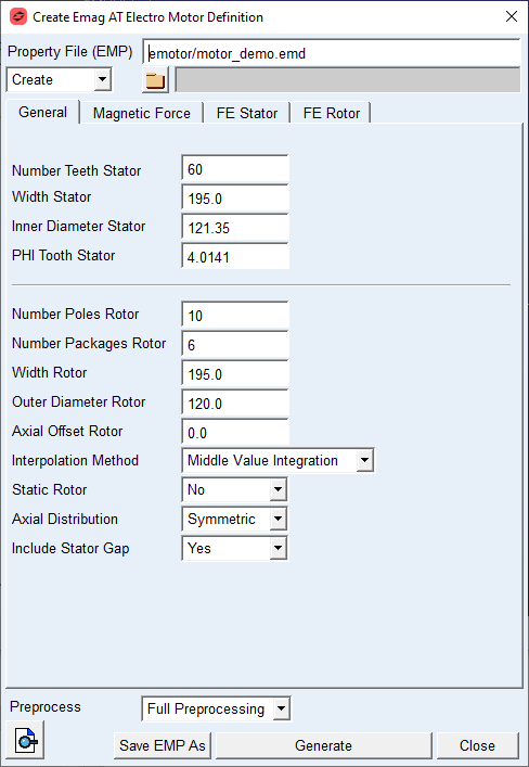
Figure 7 EMP Preprocess - General tab
Extended Definition:
Width Stator
The value defines the true width of the stator structure as the stator is usually part of housing or another belonging structure. See Figure 8.
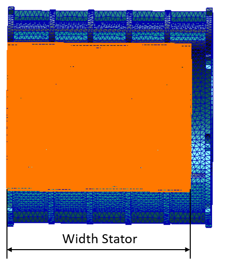
Figure 8 Width Stator
Inner Diameter Stator
The value defines the inner diameter of stator structure, resp diameter of surface formed by stator teeth tips. See Figure 9
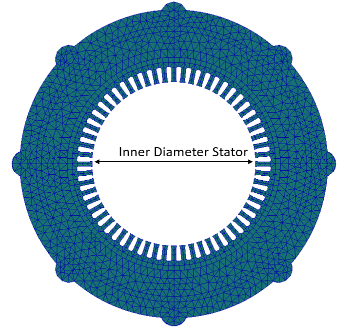
Figure 9 Inner Diameter Stator
PHI Tooth Stator
The value defined angle spanning over stator tooth tip. See Figure 10.
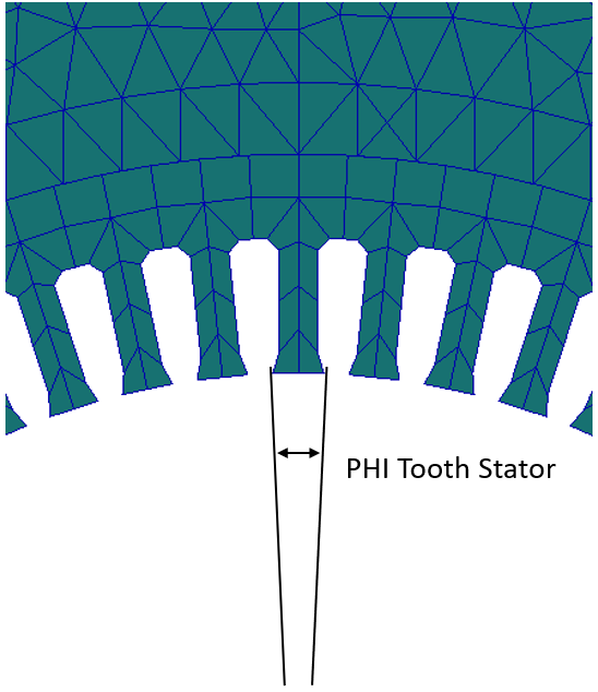
Figure 10 Stator Tooth PHI Angle
Number Poles Rotor
The value defines in how much poles is the rotor divided. For pole definition see Figure 11.
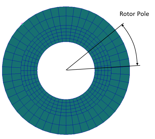
Figure 11 Rotor Pole
Number Packages Rotor
The value defines in how many segments a rotor is divided along the width. See Figure 12.
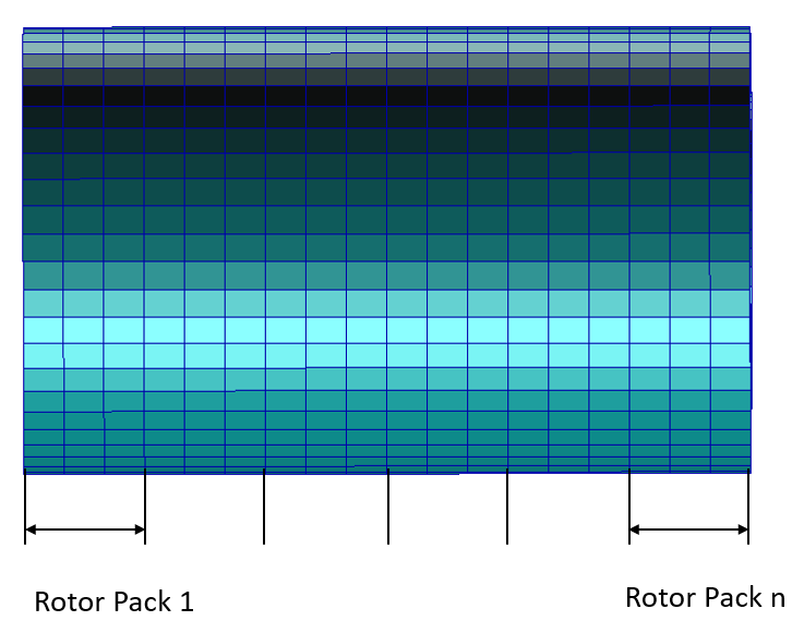
Figure 12 Rotor Package
Width Rotor
The value defines the true width of rotor structure as the rotor is usually part of shaft or another belonging structure. See Figure 13.
Outer Diameter Rotor
The value defines the outer diameter of rotor structure which forms the air gap between rotor and stator. See Figure 13.
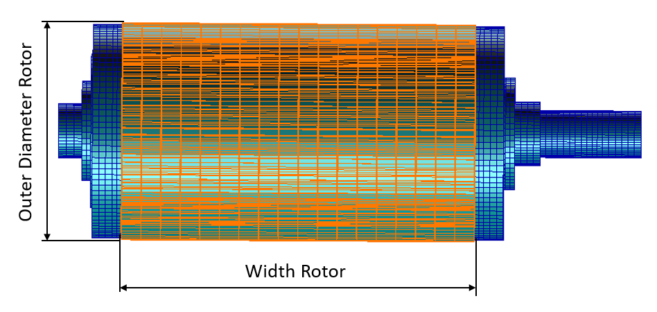
Figure 13 Rotor Width and Outer Diameter
Axial Offset Rotor
The value defines the axial shift between rotor and stator. In this release the parameter is not supported, so always zero offset is expected.
Interpolation Method
To calculate FE Grid force out of the magnetic force density, one needs to calculate surface of FE element belonging to the particular FE grid and multiply it with force density above this surface.There are three methods available for calculating the force density above the FE element. Two of them are based on middle value calculation above surface of FE element and one on local value interpolation on FE grid position. The middle value can be calculated with simple average method, see Equation (1) or more advance using Integration, see Equation (2).
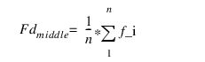 | (1) |
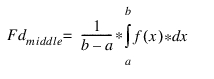 | (2) |
Static Rotor
This option either holds the rotor in the same position during force preprocessing, or enables rotation within one pole angle during the force preprocessing.
Axial Distribution
This setting influences how the resulting force on rotor pack is axially distributed to the FE grids.In Figure 14 i.e. for 3 FE elements per rotor pack the symmetric option evenly distributes the force over the 4 grids, while the shared grid between packs takes same amount of force from both adjacent packs, in contrast for unsymmetrical option the shared grid takes force only from pack 2, while there is no force contribution from pack 1.
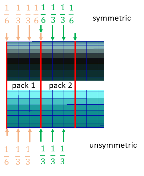
Figure 14 Axial distribution of pack force
Include Stator Gap
This option influences how the forces are calculated on stator tooth FE grids. In Figure 15 there are 3 FE grids per tooth, in case no gap is considered the first and last tooth FE grid force contribution is limited on half of the FE element surface, hence also, half the force density acting on this area. In case tooth gap is considered, the gap is split into 2 half and the first and last tooth FE grids share also load acting over the gap surface.
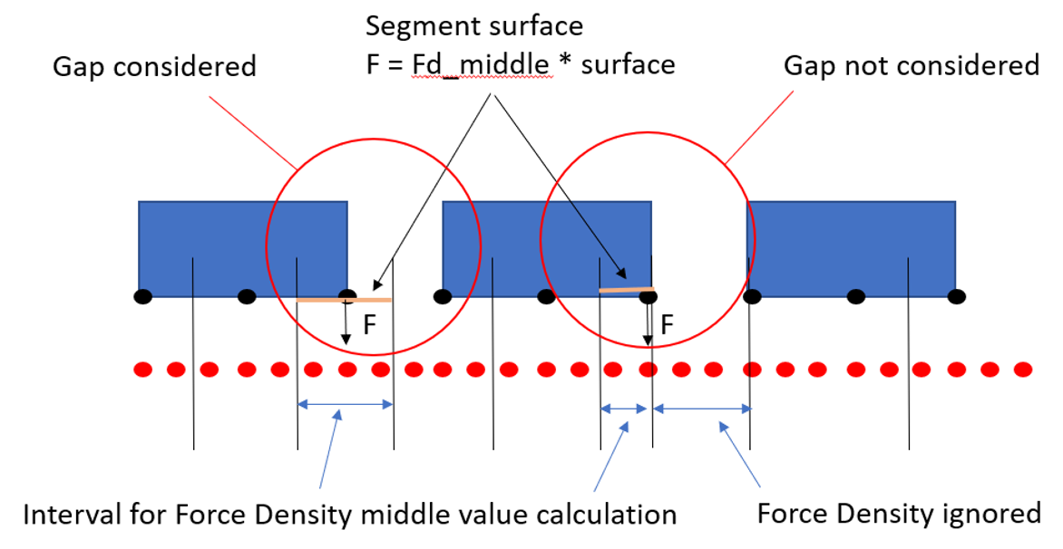
Figure 15 Consideration of tooth gap on stator
Magnetic Force
The excitation by magnetic force acting on rotor and stator is defined on this card, see Figure 16.
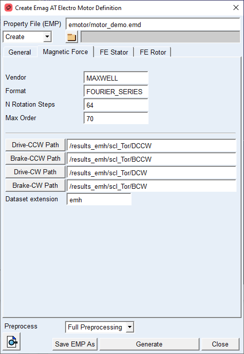
Figure 16 Magnetic Force Definition
Here the pre-calculated datasets coming from magnetic simulation are referenced for each Motor Operation Quadrant, see Figure 17.
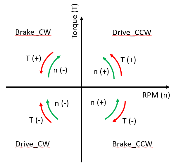
Figure 17 Motor Operation Quadrants
Each quadrant is further described with a set of operation points for given rotor torque demand and rotor RPM. Each operating point is a table of amplitudes and phases defining Fourier series for each spatial coordinate δ on magnetic data mesh and for each rotor package, see Figure 18.
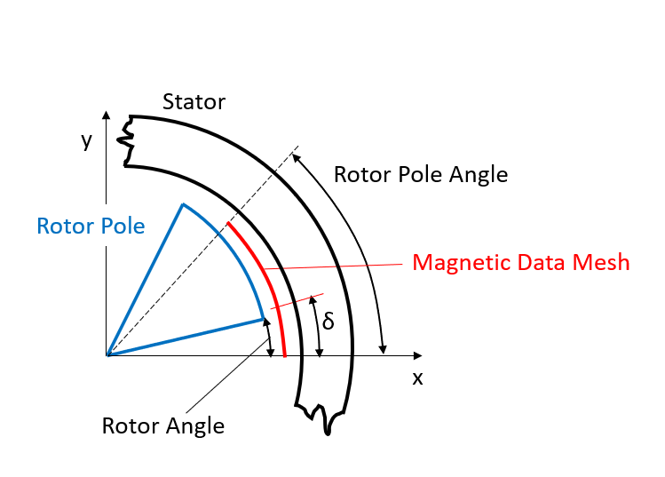
Figure 18 Rotor and Stator system in magnetic simulation
The Fourier series for each spatial coordinate describes a function of magnetic force density in respect to Rotor Angle is given by:
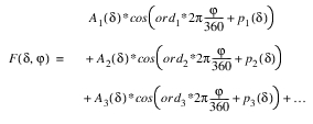
where,  is the i-th Amplitude at δ position
is the i-th Amplitude at δ position is th i-th phase at δ position
 is the i-th Motor Order
i is from 0 to Max_Order.
In the Magnetic force preprocessing, the continuous Fourier series for each spatial coordinate is discretized into n_rotational steps within one pole angle. The discretization allows to pre-calculate for each stator and rotor surface grid a discrete tangential and radial magnetic force as function of rotor rotational speed, rotor angle and torque demand.
For the options | Do the following |
|---|---|
Vendor | Informative parameter defining provider of magnetic calculations. |
Format | Informative parameter defining format of magnetic data input |
N Rotational steps | This value defines the number of discrete angular positions within rotor pole angle at which the magnetic forces are evaluated. A good starting value is 64 steps. |
Max Order | This value sets the maximal motor order to be evaluated during magnetic force preprocessing |
Drive CCW path | This parameter sets path to folder with operation points files for Drive CCW Quadrant, see Figure 17. |
Brake CCW path | This parameter sets path to folder with operation points files for Brake CCW Quadrant, see Figure 17. |
Drive CW path | This parameter sets path to folder with operation points files for Drive CW Quadrant, see Figure 17. |
Brake CW path | This parameter sets path to folder with operation points files for Brake CW Quadrant, see Figure 17. |
Dataset Extension | This parameter sets the file extension which is searched in the paths specified for Motor Operation Quadrants. |
Extended definition:
Max Order
The pre-calculated results from magnetic simulation are stored in time domain. This data is transformed into frequency domain using FFT, as a result the signal is decomposed in n-order, without any limitation. During the magnetic force preprocessing the max order taken into force density evaluation can be limited by this parameter.
Drive/Brake CCW/CW Path
Path to operation quadrants, the path can be browsed or copy pasted to the corresponding field. Files in corresponding folder and with defined extension are automatically referenced in the property file EMP and used for magnetic force preprocessing.
FE Stator
The structure of stator part is defined in this tab, see Figure 19. The data entered in this tab are used for definition of Nastran FE model for flexible body representation of housing and stator component. Those are later used in Adams model. Data from this tab is also used during magnetic force pre-calculation in order to prepare force for each FE grid on stator surface forming the air gap between rotor and stator.
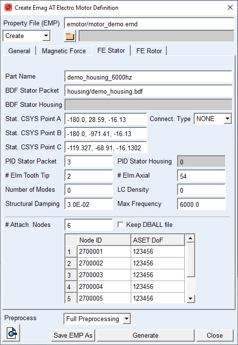
Figure 19 Stator structure definition
For the options | Do the following |
|---|---|
Part Name | This parameter defines the name of Nastran deck for MNF calculation. The name has following structure: part_name_sol103.bdf. |
BDF Stator Packet | This parameter defines name of isolated stator Nastran model, or full Nastran model including stator and housing assembly. |
BDF Stator Housing | This parameter defines name of isolated housing model in case the stator and housing are provided as separate parts. |
Stat. CSYS Point A | The value is used to define origin of local coordinate system, see Figure 20. |
Stat. CSYS Point B | The value is used to define direction of Z axis of local coordinate system, see Figure 20. |
Stat. CSYS Point C | The value is used to define X axis of local coordinate system, see Figure 20. |
Connect. Type | Select GLUE option when there are separate FE structures of housing and stator to be glued together using nastran glue contact or NONE in case single FE structure is provided. |
PID Stator Packet | This value defines Property ID of housing solid elements used to define 3D contact region for permanent glued contact. |
PID Stator Housing | This value defines Property ID of housing solid elements used to define 3D contact region for permanent glued contact. |
# Elm Tooth Tip | This value defines a number of elements over the stator tooth tip. Supported are 2 and 4 elements corresponding to 3 resp. 5 grids on tooth tip. |
# Elm Axial | This value defines the total number of elements over the stator length. |
Number of Modes | The value defines how many modes will be extracted for the MNF representation of stator and housing assembly, if set to zero, the number of modes is defined automatically by Max Frequency parameter. |
LC Density | The value defines how many residual vectors are created to append the modal basis of MNF for stator and housing assembly. Value greater than 2 does not make much sense, as the number of modes is larger than for case where Max Frequency is defined. |
Structural Damping | The value defines structural damping in the form of percentage of modal deformation for given mode. This damping is in contrast to modal damping proportional to deformation. The damping matrix is generated and stored in MNF file of stator and housing assembly. |
Max Frequency | The value defines cut off frequency for mode extraction during MNF generation process, the parameter is active if Number of Modes is set to zero. |
#Attach. Nodes | The value defines how many ASET nodes are defined for the housing and stator assembly, the detail for each node is defined in corresponding table. |
Keep DBALL file | If checked the DBALL file is preserved for later use by Nastran SOL112 procedure. |
Extended definition:
BDF Stator Packet / BDF Stator Housing
The stator resp. stator and housing structure is represented by provided Nastran models. The Stator and Housing assembly model can by represented either as separate stator part and corresponding housing part, or as a full model of housing including stator. In case of two separated FE structures are used, the Connect. Type has to be set to GLUE option. If a full model is provided the field BDF Stator Packet has to be used and Connect. Type has to be set to NONE.
Stat. CSYS Point A, B, C
The local coordinate system of stator part is defined by Nastran coordinate system convention, The cylindrical system is defined by three points, see Figure 20.
It is important to define the coordinate system on rotational axis and in stator width half. The Z axis orientation should be set as follows; the rotation with positive sense about this axis should belong to Drive CCW quadrant of Motor operation. The X axis should point to one of the teeth center grids and indicates the pole start resp, the orientation of X axis of Magnetic force calculation system. This coordinate system is used for FE grids detection belonging to Stator surface forming the air gap and at the same time as coordinate system for modal shapes extracted by MNF generation.
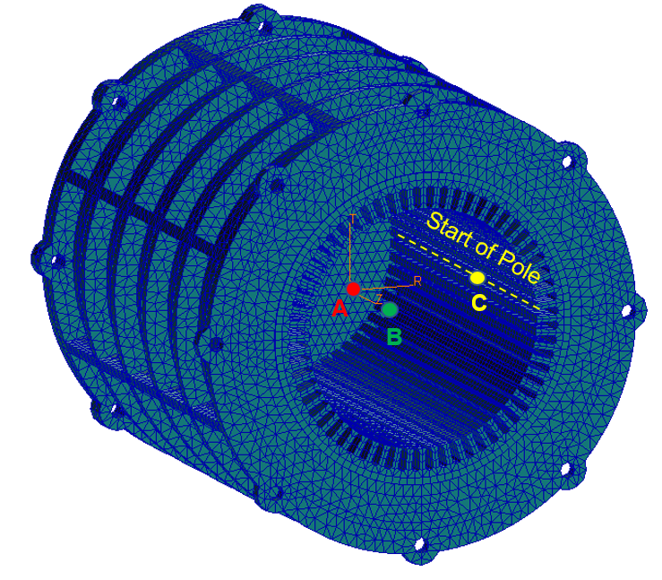
Figure 20 Stator local coordinate system definition
# Elm Axial / # Elm Tooth Tip
For stator structure the FE mesh resp. surface forming the air gap is described by number of elements on tooth tip and number of elements in axial direction along full stator length, see Figure 21, since in contrast to rotor, there are no discrete packages defined on stator. Ideally the total number of elements on stator along axial direction is a multiple of rotor packages, so there is always the same number of elements corresponding to one rotor package.
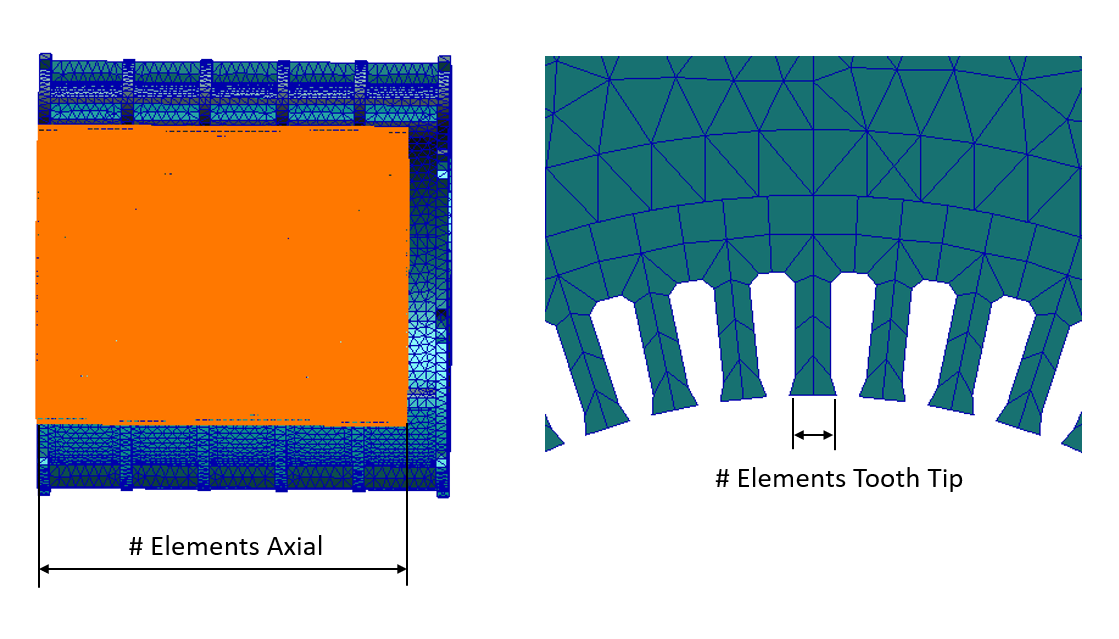
Figure 21 # Elements definition stator
LC Density
The residual vectors are present in form of radial load defined on stator surface forming motor air gap, they are equidistantly distributed over stator circumference and width. Setting value to 0 deactivates residual vectors, setting to 1 creates n_poles * (n_packs+1) residual vectors, setting to 2 creates 2*n_poles * (2*n_packs+1) residual vectors and so on. The residual vectors together with the lower number of fixed boundary normal modes defined by Number of Modes parameter should form smaller but equivalent modal base as compared to complete but large modal base extracted if defined by Max Frequency parameter.
FE Rotor
The structure of rotor part is defined in this tab, see Figure 22. The data entered in this tab are used for definition of Nastran FE model for flexible body representation of shaft and rotor component. Those are later used in Adams model. Data from this tab is also used during magnetic force pre-calculation in order to prepare force for each FE grid on rotor surface forming the air gap between rotor and stator.
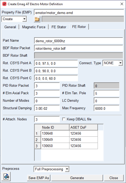
Figure 22 Rotor structure definition
For the options | Do the following |
|---|---|
Part Name | This parameter defines the name of Nastran deck for MNF calculation. The name has following structure: part_name_sol103.bdf |
BDF Rotor Packet | This parameter defines name of isolated rotor Nastran model, or full Nastran model including rotor and shaft assembly. |
BDF Rotor Shaft | This parameter defines name of isolated shaft model in case the rotor and shaft are provided as separate parts. |
Rot. CSYS Point A | The value is used to define origin of local coordinate system, see Figure 23. |
Rot. CSYS Point B | The value is used to define direction of Z axis of local coordinate system, see Figure 23. |
Rot. CSYS Point C | The value is used to define X axis of local coordinate system, see Figure 23. |
Number Teeth Spanned (k) | Number of teeth spanned can be used to indirectly define the tooth thickness allowance together with Effective Base tangent length. The number of teeth the instrument is placed over, depends on the total number of teeth, the pressure angle and helix angle of a gear. |
Connect. Type | Select GLUE option when there are separate FE structures of shaft and rotor to be glued together using nastran glue contact or NONE in case single FE structure is provided. |
PID Stator Packed | This value defines Property ID of rotor pack elements, by this ID the glue contact can find elements to glue together |
PID Stator Housing | This value defines Property ID of shaft elements, by this ID the glue contact can find elements to glue together. |
# Elm Tan. Pole | This value defines the number of elements along one rotor pole circumference. |
# Elm Axial Pack | This value describes how many elements are defined per one rotor pack axially. |
Number of Modes | The value defines how many modes will be extracted for the MNF representation of rotor and shaft part, if set to zero, the number of modes is defined automatically by Max Frequency parameter. |
LC Density | The value defines how many residual vectors are created to append the modal basis of MNF for rotor and shaft assembly. Value greater than 2 does not make much sense, as the number of modes is larger than for case where Max Frequency is defined. |
Structural Damping | The value defines structural damping in the form of percentage of modal deformation for given mode. This damping is in contrast to modal damping proportional to deformation. The damping matrix is generated and stored in MNF file of rotor and shaft assembly. |
Max Frequency | The value defines cut off frequency for mode extraction during MNF generation process, the parameter is active if Number of Modes is set to zero. |
# Attach. Nodes | The value defines how many ASET nodes are defined for the rotor and shaft assembly, the detail for each node is defined in corresponding table. |
Keep DBALL file | If checked the DBALL file is preserved for later use by Nastran SOL112 procedure. |
Extended definition:
BDF Rotor Packet / BDF Rotor Shaft
The rotor resp. rotor and shaft assembly is represented by provided Nastran models. The rotor and shaft assembly model can by represented either as separate rotor part and corresponding shaft part, or as a full model of shaft including rotor. In the case of two separated models the Connect. Type has to be selected to GLUE. If a full model is provided the field BDF Stator Packet has to be used and Connect. Type has to be set to NONE.
Rot. CSYS Point A, B, C
The local coordinate system of rotor part is defined by Nastran coordinate system convention, The cylindrical system is defined by three points, see Figure 23.
It is important to define the coordinate system on rotational axis and in rotor width half. The Z axis orientation should be set as follows; the rotation with positive sense about this axis should belong to Drive CCW quadrant of Motor operation. The X axis should point to one of the rotor outer surface grids and indicates the pole start resp, the orientation of X axis of Magnetic force calculation system. This coordinate system is used for FE grids detection belonging to rotor surface forming the air gap and at the same time as coordinate system for modal shapes extracted by MNF generation
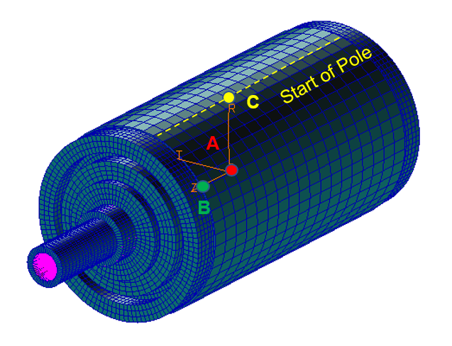
Figure 23 Rotor local coordinate system definition
# Elm Axial Pack / # Elm Tan. Pole
For rotor structure the FE mesh resp. surface forming the air gap is described by number of elements on rotor pole and number of elements in axial direction along rotor pack width, see Figure 24.
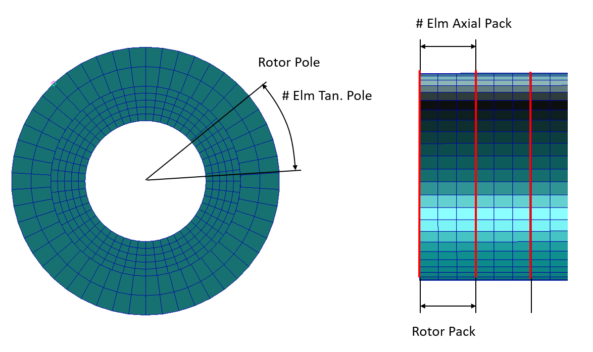
Figure 24 # Elements definition rotor
LC Density
The residual vectors are present in form of radial load defined on rotor surface forming motor air gap, they are equidistantly distributed over rotor circumference and width. Setting value to 0 deactivates residual vectors, setting to 1 creates n_poles * (n_packs+1) residual vectors, setting to 2 creates 2*n_poles * (2*n_packs+1) residual vectors and so on. The residual vectors together with the lower number of fixed boundary normal modes defined by Number of Modes parameter should form smaller but equivalent modal base as compared to complete but large modal base extracted if defined by Max Frequency parameter.