KISSsoft Gears
Rather than defining a gear profile in Gear AT you might want to use one defined in KISSsoft already. This import functionality provides you quick and seamless way to translate KISSsoft gear data and preprocess all relevant files required to build Gear AT Elements and Gear AT Force in your Adams model.
Current Gear AT release supports import of text reports created for single gear *.Z11, cylindrical gear pair *.Z12, planetary gear *Z14 and tree gears train *.Z15. The direct import of *.Z1x files was dropped in this release.
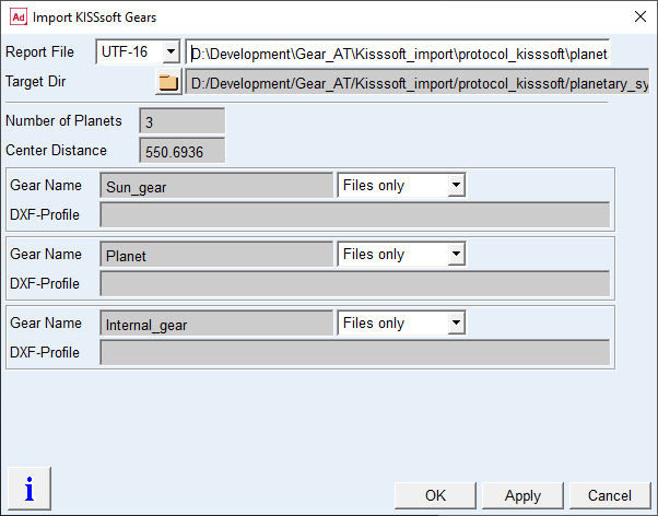
Figure 161 KISSsoft import dialog box
For the options | Do the following |
|---|---|
Report File | Select your report in form of *.txt file exported from KISSsoft. To create the report follow the steps described in this chapter |
Target Dir | Select folder where in created folder Gears all gear files will be stored under gear name subfolders. The Default location is the report location |
Number of Planets | This label and field appear only for planetary system and shows the number of planets as defined in the input deck. *.Z12 files always have zero planets, *.Z14 files show a number higher than zero. |
Center Distance | This label and fields appear for all supported export types and shows center distance for gear stages except single gear. |
Gear Name | The names of the gears from the input KISSsoft report file are shown. They consist of the file name and the gear number or description according to the input deck. The names can be changed but should be unique within your entire model |
Files only / Flex Tooth | Make your choice for the level of gear data translation and preprocessing: ■Files only: it represents Gear AT Shape Definition preprocessing; it translates data from report file and writes all gear property files (CGP, CGD, OPT) required for the Gear AT Mesh preprocessing ■Flex tooth: it represents Gear AT Mesh pre-processing; the background processes are executed to generate all files (CGS, SHL) to create gear and gear force elements for your Adams model |
DXF-Profile | Browse for *.dxf file to use half tooth profile exported from KISSsof. This ensures that your KISSsoft profile is used. Keep none to use profile generated by Gear AT profile generator. Important: be careful not to change the KISSsoft profile stored in *.CGP by generating new profile via Gear AT Shape Definition dialog box. If the KISSsoft profiles are provided the reference to definition file in CGP is set to “by kisssoft” so the Shape Definition knows the source is not the definition file and hence it does not overwrite the profile until the user unlocks the file. Note that you can still edit modifications or deviations by modifying Gear AT Element |
Tooth geometry
The current import process support only Tooth shape parameters defined in cards Reference profile and Manufacturing, data from those two cards is indicated in the Tooth form card as Automatic Operation. Data from automatic operations is therefore stored in the generated report.
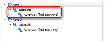
One can deactivate those automatic operations and create custom operations, however those data is then independent from the cards Reference profile and Manufacturing and is not reflected in the generated report, so it would not be correctly set with the import operation in Gear AT. For this reason, those custom operations are not supported in this Gear AT release.
Important note is about the setting in reference profile card where the machining with final stock is available only in combination with hobbing cutter.
Topology modifications
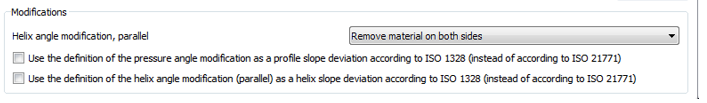
The import process is translating the topology modifications defined in KISSsoft into definition used in Gear AT. Especially the slope definitions along profile and lead direction have multiple conventions. Gear AT adopted the ISO 1328 definition, where the slope is identical to deviation of profile resp. lead slope. KISSsoft per default uses DIN 21771 definition for slopes. This can lead to different values for slope definition but should lead to the same modification. The option used in KISSsoft can be checked under Calcualtions -> Settings -> General card.
The topology modifications along profile height are usually defined between so called Control diameters dSa resp. dSf in KISSsoft. Values of those diameters is dependent on the settings in Manufacturing tab.
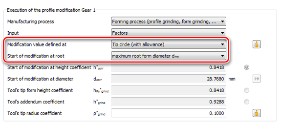
The control point at end ( tip) is defined with options in Modification value defined at ( Tip circle theoretical / allowance, Tip form circle theoretical / allowance ). The current Gear AT release supports all those options. The control point at start ( root) is defined with option in Start of modification at root . There are multiple options, also dependent on manufacturing steps, the current Gear AT release supports the options ( minimum active root diameter dNfi, maximum root form diameter dFfe and average diameter ( dFfe + dNfi)/2 ). Other options are not translated; thus, user has to correct the required value manually in Gear AT input mask.
Below is a table with relations between KISSsoft topology settings and Gear AT.
For the options | Do the following |
|---|---|
Tip relief linear Root relief linear | Supported with tip / root linear relief |
Tip relief arc like Root relief arc like | Supported with tip / root quadratic relief |
Tip relief progressive Root relief progressive | Supported partially with tip / root quadratic resp. cubic relief. If the outcome of c/5 is below 1.5 the system sets linear shape, between 1.5 and 2.5 quadratic shape is used and above 2.5 cubic shape is used |
Tip relief linear with transition radius Root relief linear with transition radius | Partially supported either with linear or quadratic tip / root relief |
Profile crowning roll length centered Eccentric profile crowning Profile crowning diameter centered | Supported with quadratic barreling |
Shortened profile crowning Tip relief linear with profile crowning | Those two modifications act together and are partially supported; however, they are not automatically converted. User can manually adjust barreling and tip relief to get similar shape of modification |
Pressure angle modification value | Supported with profile slope |
Pressure angle modification angle | Not supported |
End relief I End relief II | Supported with linear end reliefs |
End relief I arc like End relief II arc like | Supported with quadratic end reliefs |
Flank line crowning side I Flank line crowning side II | Supported with quadratic end reliefs |
Helix angle modification parallel value Helix angle modification tapered or conical | Supported with lead slope |
Helix angle modification parallel angle | Not supported |
Flank line crowning Eccentric flank line crowning | Supported with quadratic crowning |
Triangular end relief I Triangular end relief II | Not supported |
Twist | Supported with profile twist |
Twist caused by manufacturing | Not supported |
Prior to importing data in Adams you have to prepare them and export in appropriate format. The steps to take in KISSsoft are described in following section.
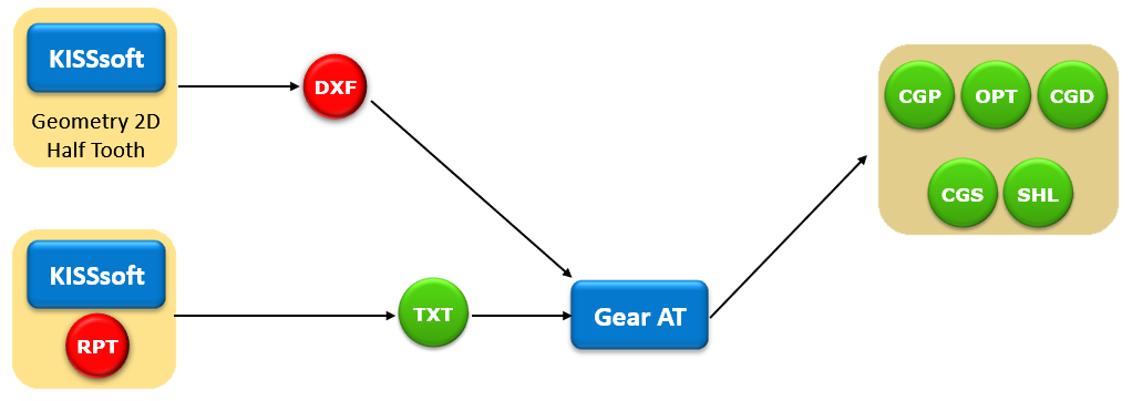
Figure 162 Import KISSsoft gear profile data flow
Export of KISSsoft Report
In order to export Gear AT readable format file you need to instruct KISSsoft to use the user-defined report instead of standard one. The current Gear AT version provides report templates for Z11 or Single gear, Z12 or Gear pair and Z14 or Planetary stage modules. To make it, you need to do following before start of KISSsoft:
1. Copy report from Gear AT to KISSsoft installation:
a. Copy file from <<Gear_AT_Install_dir>>\2021_0\gear_at\common\Z01xLe0.RPT to folder <<KISSsoft_install_dir>>\ext\rpt
b. Depending on the language the letter „e“ in Z01xLe0.RPT has to be changed to reflect your preference; (d = German, e= English, read KISSsoft help document for more information)
2. Start KISSsoft and open input deck of the model to be exported to Gear AT:
a. Display Tooth form Card in Calculation -> Tooth Form menu if not displayed already
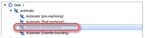
b. If microgeometry modifications are present, deactivate the item in the gear tree for each gear in the Tooth Form card, doing so sets the forming diameters in additional report information without influence of microgeometry. This is essential if exported profiles are used as well during the import in Gear AT, as those basic diameters from report are used to identify different parts of gear profile (that is, root, involute, tip chamfer, …)
c. After selection of the Tooth form card hit the calculation button and run the calculation. This generates temporary file with detailed information about profile cutting
d. Select some other card like Basic data and run the calculation again by pushing the calculation button
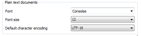
e. Check the report setting in Report -> Settings -> Editor card and set the Default character encoding to either UTF-16 or UTF-8, those two are supported in Gear AT import.
f. Now staying in the Basic card and generate the report under Report -> Generate
g. The report should have specific formatting including line “Hexagon – Gear AT Import Report” in the upper part of the report
h. Save the report as text in your Adams working directory via Report – Save as; select Save as type to be ANSI text (*.txt)
i. Use this file as input KISSsoft Report file in Import – KISSsoft Gears dialog box as shown on Figure 162.
j. If you prefer to use a tooth profile generated in KISSsoft proceed with export of 2D geometry as shown in the next section
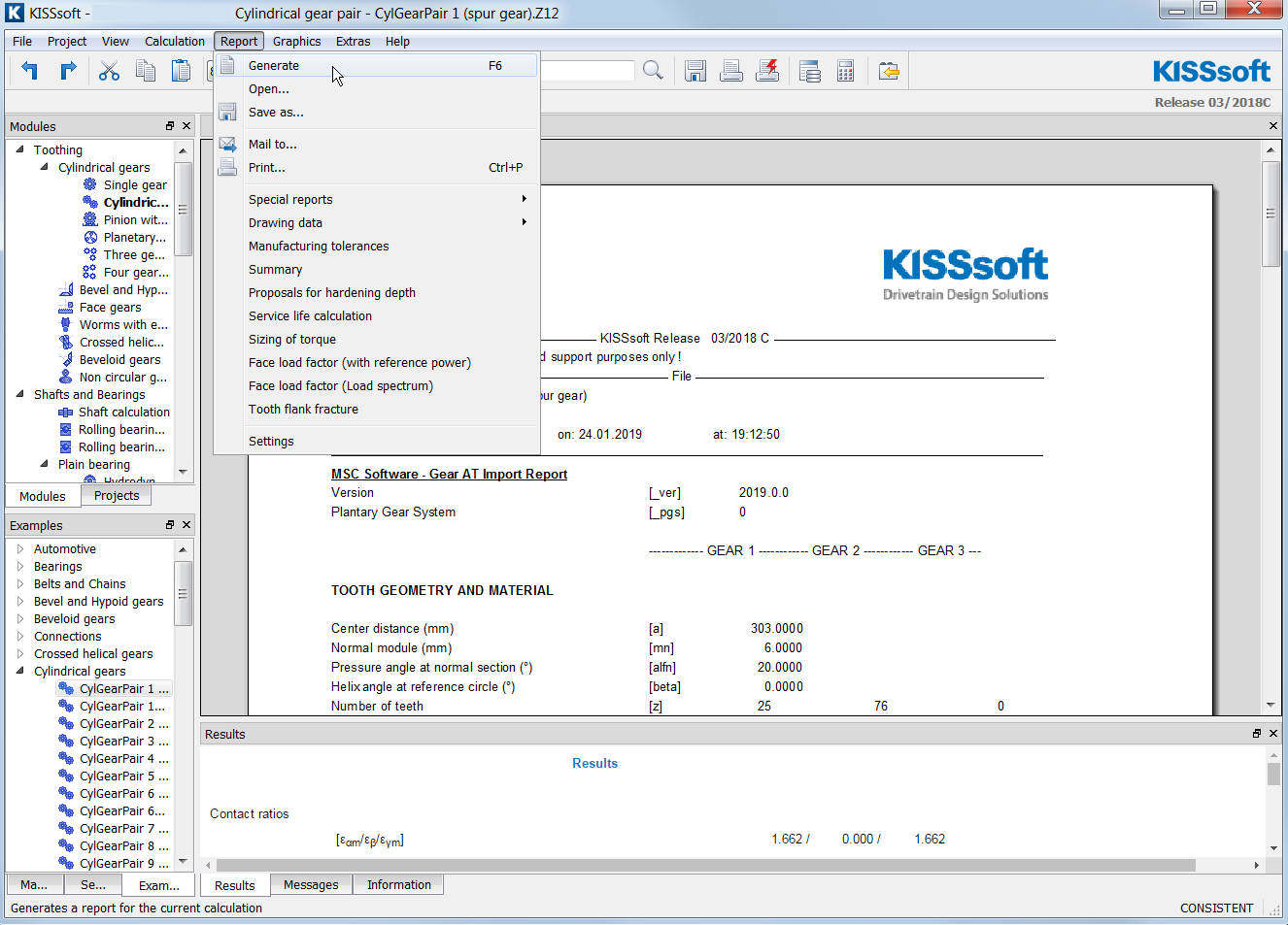
Figure 163 Export KISSsoft report for Gear AT
Export of a gear tooth profile in DXF format (optional)
Once your gear expert has designed a gear stage to be analyzed in Adams you most probably prefer to use a tooth profile generated in KISSsoft rather than the one generated in Gear AT. To do that you need to export 2D geometry of each gear in the gear stage along with report file described in Export of KISSsoft Report chapter.
The exported profiles can be used also for comparison with generated profiles with Gear AT. One can import the dxf profile in the Profile Preview dialog box.
To export tooth profile for gear definition do following in KISSsoft:
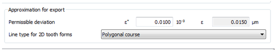
1. Check that Permissible Deviation in Tooth Form card is sufficiently small, that is, epsilon <= 1.0 E-3 (go to Calculation – Tooth Form – Approximation for export)
2. Run calculation
4. Open the Property tab and toggle off all displayed profiles except the profile you wish to export
5. Switch the Section to Transverse, half tooth right (in KISSsoft Version 2020)
6. From Geometry 2D window save the profile in DXF format by pushing Save as button; select Save as type to be Drawing Exchange Format (*.dxf)
7. Switch to Tooth form Gear 2 and repeat steps from 3.to 5. to export profile of the second gear
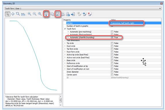
Figure 164 Export gear profile from KISSsoft
Figure 165 Export gear profile from KISSsoft