Measurement Protocol
Gear AT Measurement import enables you to extract gear topology and macro-geometry data from measurement protocol file ( MKA ), out of which one can get a basic set of property files for definition and further adjustments of macroscopic profile data. The basic file set comprises Property file ( CGP ), Definition file ( CGD ) and Measurement file ( CGM ). Figure 144 shows how to access the Import tools.
Results from measurement preprocessing are stored in CGM file. The CGM stores the adjusted data from MKA file in proper format for Gear AT environment. The file names, (CGD ,CGP and CGM ) are derived from input file name, one can edit them if required. All three files ( CGP, CGD and CGM ) are created after hitting "Generate" button automatically from the data and according to boundaries set in the Measure card.
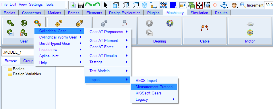
Figure 144 Access to Measurement Import tools
The Gear AT measure file (CGM) can be referenced in the property file (CGP) so it appears in the shape definition Windows. Once the Measure file exists the Measure card is active and provides preview features for the measurement and adjustment of active diameters.
There is a change in dataflow from the measurement file into the Gear AT Solver in this release. In the past releases the CGM file was processed during Gear AT Standard preprocessing and the measurement data was stored in the CGS file, this was a disadvantage as the change in measurement data required new preprocessing run.
The dataflow was improved in the sense that the CGM file is no longer processed in the Gear AT Standard preprocessing, but the measurement data is directly feed into the Gear AT Solver, what makes the measurement data exchange easy and quick. The dataflow comparison is visualized on Figure 145
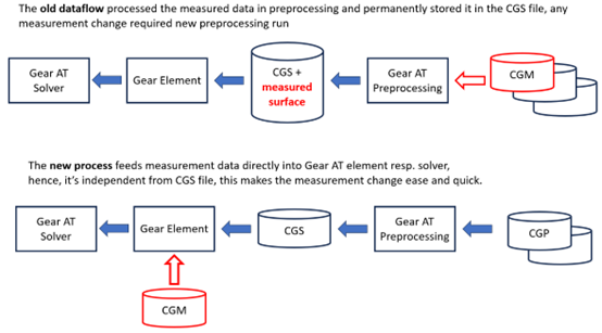
Figure 145 Old vs New measurement dataflow
The measure file can be replaced or added and or removed under modifying of gear element. The data from the measure file are loaded by the Gear AT solver and the measurements are applied at the simulation start once the activity flag in gear element is set.
The Gear AT Measurement Input has following tabs to help you extract and setup gear topology:
For the options | Do the following |
|---|---|
Protocol file (MKA) | In this field a measurement protocol file can be selected for import. Input parameters for basic tooth profile are initialized in the dialog box and measurement data can be visualized. |
Property file (CGP) | This file stores all basic geometrical parameters, profile curve, microgeometry and deviations data required for gear element preprocessing and building the gear element in your Adams model. |
Definition file (CGD) | This file stores all basic gear and tool parameters and settings for a gear profile generation one can usually find in a gear datasheet. |
Measure file (CGM) | The CGM file stores the surface deviations data from MKA in proper format, reflecting the user adjustment in the dialog box. |
CGP Create toggle | In case one is interested in generation of the CGM file only, the user can deactivate generation of a gear property file. |
CGD Create toggle | In case one is interested in generation of the CGM file only, the user can deactivate generation of a gear definition file. |
Adjust Profile | Open the Shape Definition Dialog box to adjust the profile details which are not included in the measurement protocol file ( MKA ). |
In the first step all required parameters are extracted from Input file ( MKA ). Outcome of extraction process is displayed in text form and stored as log file. In case some required parameters are not found or cannot be extracted successfully, message about this issue is displayed and default value for given parameter is used. Usually the MKA file contains beside the measurement also basic tooth profile parameters and radial and pitch deviations for each tooth flank.
Supported MKA file Structure
The MKA file can differ in the way the data is measured, what additional parameters are stored in the header part and finally in language and units used. Most relevant format specific settings are stored in the Header section. The current implementation supports German language and length defined in [mm]. Below the bolted lines are required for adjusting the extraction process. In case UNDEFINED is not present, this value is set to 1000 microns. User can adjust this value later in the dialog box.
HEADER KS.MK.FILE
■TYPE STI
■VERSION 410.0/1
■SEPARATOR:
■UNITS mm
■ANGLE decimal
■PROFILE diameter
■LANGUAGE 0 DEU
■UNDEFINED - 2147483.648
Following the Header section, gear and measurement parameters are defined, where each parameter in MKA file has unique line key at the line beginning. This enables robust identifications of parameters. Below is the list of required lines:
■21:Normalmodul mn................ [mm]....: xx
■22 :Zähnezahl z.............................: xx Außenverzahnung
■23 :Schrägungswinkel ß .......... [Grad]..: xx°xx'xx" rechts rechts
■24 :Eingriffswinkel alpha ........ [Grad]..: xx°xx'xx"
■25 :Profilverschiebungsfaktor x ............: xx
■26 :Zahnbreite ................... [mm]....: xx
■27 :Kopfkreisdurchmesser da ...... [mm]....: xx
■272 :Fußkreisdurchmesser ............[mm]....: xx
■28 :Kugeldurchmesser ............. [mm]....: xx
■281 :Messzähnezahl=..........................: x
■41 :Start Messbereich.................................ds= [mm]..: xx xx
■44 :Ende der Messstrecke...........................damax= [mm]..: xx xx
■47 :Teilungsmesskreis =xxxx.xxxx (Kugel-R =x.x) [mm]..........: xx.xx
■61 :Messanfang (unten)................................ba [mm]...: x.xx x.xx
■64 :Messende (oben)...................................be [mm]...: x.xx x.xx
■111 :Diam. Zweikugelmaß: MDK:xx : xx : xx
■115 :ZahnweitenmaŢ: WKT: xx : xx : xx
These parameters are used to construct the basic tooth profile and determine the measurement area.
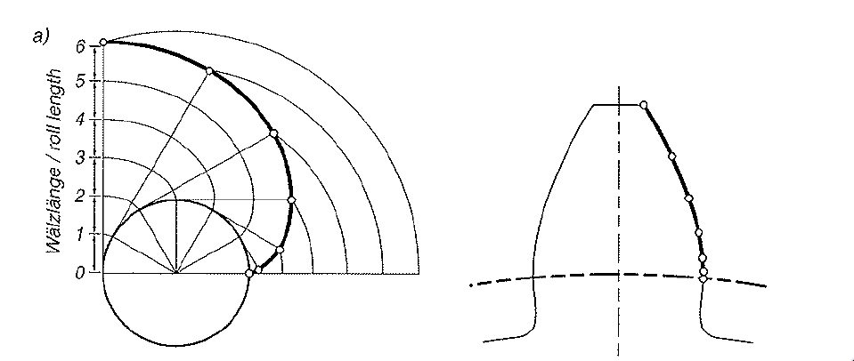
Figure 146 Measured points distribution on involute
The import process supports two types of data measurement format. One of the supported formats is a measurement for 1 profile curve typically in the middle of gear width and 1 lead curve typically about middle of the tooth height for each tooth, this format can be further refined by measuring 3 profile curves and 3 lead lines, then also the flank twist can be captured. These two types of measurements are referred as Simple type.
Another type of measurement consist of more the 3 profile curves and typically 1 lead line curve. This format is usually measured just over selected teeth as it is relative time consuming. This type of measurement is referred as Detailed type.
The import detects both types and either both or just one of them can be processed and stored to the Gear AT measure file for later use in simulations.
It is assumed the measurement over tooth profile is done in transversal plane and the measurement points are equidistant in regular roll angle resp. roll length of the gear, see Figure 146. The measurement can be done for multiple teeth. Those teeth measures can be processed after the import into the dialog box.
Usually, the flank measurement is supplemented with pitch and ovality error measures. The error measurement expects formatting as below, here the column Cumulative Pitch Error (Ffp) and Ovality Error (Fr) is important:
■linke Zahnflanke
■Zahn-Nr. fp Fp Fr
■1 x.xxx x.xxxx x.xxxx
■2 x.xxx x.xxxx x.xxxx
■… x.xxx x.xxxx x.xxxx
■n x.xxx x.xxxx x.xxxx
■rechte Zahnflanke
■Zahn-Nr. fp Fp Fr
■1 x.xxx x.xxxx x.xxxx
■2 x.xxx x.xxxx x.xxxx
■… x.xxx x.xxxx x.xxxx
■n x.xxx x.xxxx x.xxxx
In case those measurement blocks are not present in input file, zero deviations are assumed.
Parameters
The gear basic geometrical parameters can be found in the Parameters tab (Figure 147). Here the thickness definition can be also selected, default is set to backlash free case. There are several measurement types for gear tooth thickness evaluation. Current implementation can process Over ball Measure, and/or Tangent length measurement over given teeth number. At least one of these measures should be available to correctly adjust ideal flank position.
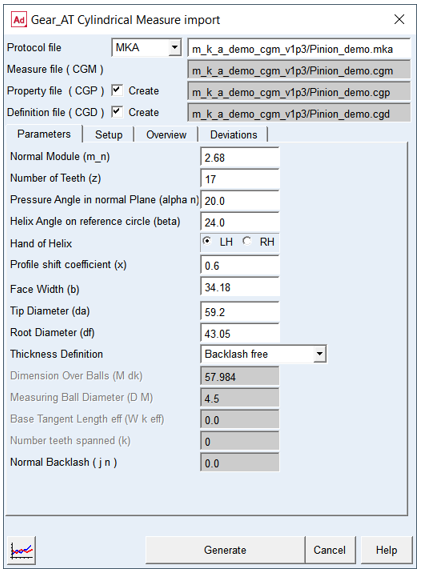
Figure 147 Diameters definition over measured Data
Most of the Parameters are identical with those in General and Tolerance card of Shape Definition dialog box. The ideal profile created based on reduced parameters found in the input file represents just an initial setup for further adjustments of tooth tip and root section in the Shape Definition dialog box. It is strongly recommended to continue import process in Shape Definition dialog box, to setup correct connection of measurement with the ideal flank on both, tip and root sections of tooth.
For the options | Do the following |
|---|---|
Normal Module (m_n) | Value of module in normal plane of tooth |
Number of Teeth (z) | Number of teeth of a gear |
Pressure Angle in normal Plane (alfa n) | Angle at the pitch diameter between the line of pressure and the line tangent to the pitch circle |
Helix Angle on reference circle (beta) | The helix angle defines the slope of the tooth in lead direction against the rotational axis at the pitch diameter. A positive sign corresponds with the right hand rule. A straight spur gear has helix angle of zero |
Hand of Helix | Defines whether the helix is left handed (negative) or right handed (positive). |
Profile shift coefficient (x) | This factor is positive, when the reference profile is moved away from a gear by the amount of module * factor. Positive factor increases tooth thickness at pitch circle while negative factor decreases. |
Face Width (b) | The length of tooth flank in lead direction. |
Tip Diameter (da) | Tip Diameter (da) |
Root Diameter (df) | The Root Diameter of measured gear |
Thickness definition | Selects which measurement is used to define tooth thickness. |
Dimension Over Balls (M dK) | The Dimension over balls can be used to indirectly define the tooth thickness allowance together with Measuring ball diameter. |
Measuring Ball Diameter (D M) | The diameter of measuring ball can be used to indirectly define the tooth thickness allowance together with Dimension over balls M dK. |
Effective Base Tangent Length ( W k eff) | The Effective Base tangent length Wk eff, which is measured over a specific number of teeth. The number of teeth the instrument is placed over, depends on the total number of teeth, the pressure angle and helix angle of a gear. |
Number teeth spanned (k) | Number of teeth used in the base tangent length measurement. |
Normal Backlash (j n) | The entered value represents the portion of the total backlash in normal plane along line of action, applied on the respective gear wheel. |
Setup
The measurement adjustment and processing can be adjusted on this tab, see (Figure 148).
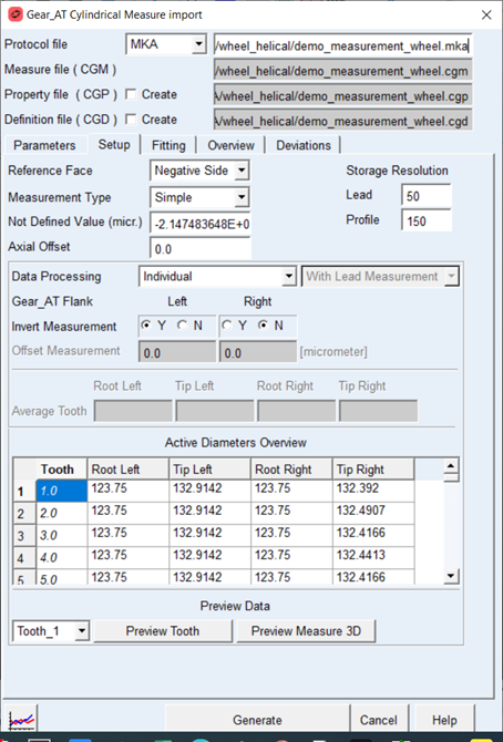
Figure 148 Measure Import - Setup tab
All detected measure types ( Simple or Detailed ) are listed in the Measure Type menu. The setting is done for both measures individually and both are stored to the Measurement File ( CGM) if selected.
Both measure types can be processed as individual measures for each tooth or averaged measure for single tooth, this depends on available data in the measurement protocol.
Both measure types can be processed as individual measures for each tooth or averaged measure for single tooth, this depends on available data in the measurement protocol.
Individual processing enables to switch sing of measure and adjusting active diameters for each tooth separately in the Active Diameter Table. The Average processing in addition enables to adjust the measurement offset and as we have only one resulting tooth the active diameters are adjusted in dedicated fields for Average tooth and the Active Diameter Table only lists the detected measures in read only mode.
The Measures are stored in the Measurement File ( CGM) as surface map for each tooth resp, averaged tooth with resolution defined by fields Lead and Profile under Storage Resolution, the default is 50 points over gear width and 150 points over gear over gear height resp over involute contour.
For measurement protocols with more the one Profile measures one can select if the lead measurement is included within the surface map or not, hence for the case the lead measure is not included the lead direction is derived from the fitting over available profile measures defined over gear width. The setting for this feature is available next to the Processing menu.
For measurement protocols with more the one Profile measures one can select if the lead measurement is included within the surface map or not, hence for the case the lead measure is not included the lead direction is derived from the fitting over available profile measures defined over gear width. The setting for this feature is available next to the Processing menu.
For the options | Do the following |
|---|---|
Reference Face | Selected options define which side of Gear AT element is used as Reference plane for applying the measurement data accordingly to measurement process. In addition, this option also defines left and right flank definition. |
Measure Type | The menu enables to switch the menu between available measure types. For the moment Simple and Detailed measure types are supported. |
Not defined Value | This value is sometime directly defined in input file, but in case it is missing, user can adjust this value. Data with absolute magnitude above this value are not plotted, neither they should be used for later use. Usually this data is results if measuring outside of gear flank. |
Axial Offset | This value enables to adjust zero offset in axial direction in case zero is not directly set on Gear Face. See Figure 149, resp. Figure 150. |
Storage Resolution Lead / Profile | The values define measurement surface map resolution stored into the Gear AT Measurement file (CGM) for each tooth resp. single averaged tooth. |
Data Processing | This option defines how the data available in protocol file is processed. Depending on the available data in protocol, the data can be processed individually for each tooth or as averaged tooth from available teeth measures. |
Invert measurement | This switch inverts the sign of measured data. Usually one of the flanks is measured with opposite sign. |
Offset Measurement | To adjust the position of the measurement in relation to ideal flank, user can select offset value, this shifts the entire deviation surface in one or another direction along the flank normal. This field is available for averaged data processing. |
Average Tooth Root_left, Root_right, Tip_left, Tip_right | Diameter from which the measurement data is applied on the tooth flank surface at the root area, resp tip areal see Figure 152. Initial value is auto-detected from Active Diameters Overview Table. This field are available for Average data processing. |
Active Diameters Overview Root_left, Root_right, Tip_left, Tip_right | Diameter till which the measurement data is applied to the tooth flank surface at the root area, resp. tip area, see Figure 152. Initial value is autodetected from Defined profile measurement values. This table can be edited for Individual data processing. |
Preview Tooth | Previews measurement data applied on ideal tooth flank geometry in form of 3D tooth model for selected tooth. |
Preview Measurement 3D | Previews deviation measurement values in form of 3d plot for selected tooth. |
Depending on the Orientation of the Gear in measurement machine and the gear element in model, user can select the Reference Face on the gear model to match the Reference Face on the measurement machine with the Reference Face switch.
The Profiles are measured from gear bottom to gear top face in the measurement machine. The default position is chosen as bottom face is located on the Gear positive side; this corresponds to option Reference Face on negative side. For this setup the tooth flanks are identical on measurement machine and in Gear AT. See Figure 149.
In case the Reference Face is chosen on positive gear side face, the bottom face is on gear negative side and the flanks are interchanged between measurement machine and gear AT. See Figure 150.
The position of the gear bottom face together with Gear AT Datum Face and measured surface can be previewed in form of 3D model, see Figure 151.
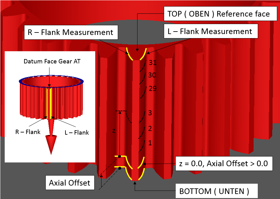
Figure 149 Reference face on Negative gear side
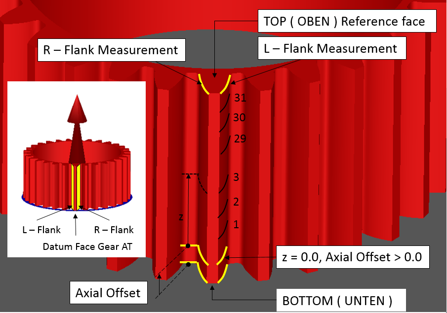
Figure 150 Reference face on Positive gear side
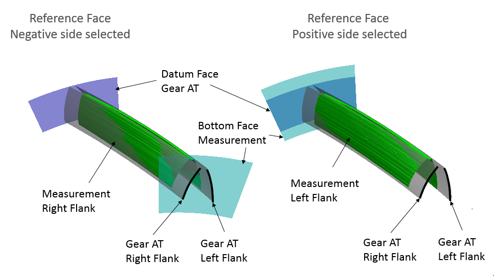
Figure 151 Switching Reference face
The measured data is stored in Measurement file (CGM) transformed to Gear AT gear element coordinate system, meaning first profile is closest one to Gear AT Datum Face. The boundaries of measurement data are defined axially and radially by set of parameters depicted on Figure 152 resp. Figure 153. Those parameters are defined in Gear AT element coordinate system.
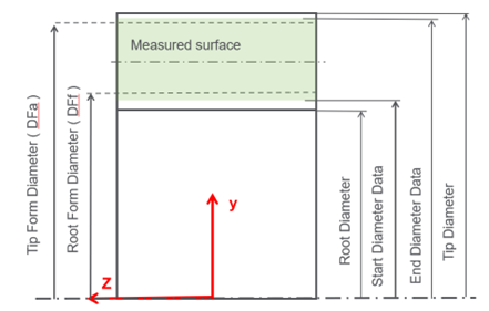
Figure 152 Radial position of measured Data
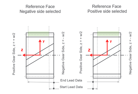
Figure 153 Axial position definition of measured Data
The tooth contour with ideal and measured flank surface can be previewed with Tooth preview button for selected tooth, see Figure 154. The pure measurement data can be previewed with Measurement preview 3D button for selected tooth, one can choose to display either left or right flank, see Figure 155. The preview is generated by default with resolution of 30 points aver lead and 100 points over profile, this can be changed based on user requirements. For Measure types with more then 1 profile measure over gear width the menu for lead setup is available, so the preview can be used to compare the effects of including the lead measurement or not, as well for previewing the raw data, resp. adjustment of the fitting spline over lead direction
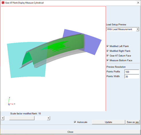
Figure 154 Tooth preview
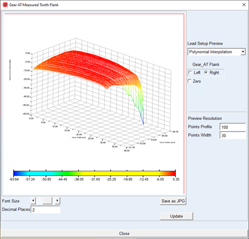
Figure 155 Measurement preview
Fitting
The Fitting tab enables to preview the raw measurement data and eliminate outlier’s values, perhaps to correct the start and end points on a measurement. In addition, the Fitting spline degree and smoothing parameter can be adjusted for each group of measures: Detailed Profile and Lead measures as well for Simple Profile and Lead measures, see Figure 156.
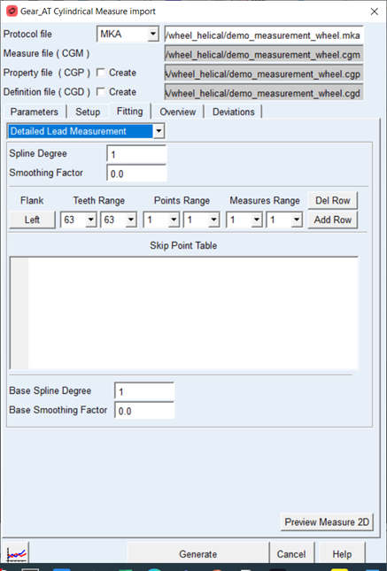
Figure 156 Measure Import – Fitting tab
The points can be skipped as individual points or range of points on single tooth or at range of teeth. Skipped points are not considered in the fitting process. At the same time the fitting spline is used also to extrapolate the measurement until the defined boundary, hence filling the gap for undefined values and or not measured portion of gear flank. The fitted and raw data can be previewed with the Preview Measure 2D button.
For the options | Do the following |
|---|---|
Spline Degree | Spline degree for data fitting for particular group of data. The values 1, 2, 3 represent linear, quadratic and cubic spline. |
Smoothing Factor | Smoothing factor enables to smooth underlining data points and hence filter out some unwanted noise in the original data. Setting it to 0 means the data is strictly interpolated over the original points. |
Base Spline Degree | Spline degree for data fitting for particular group of data. The values 1, 2, 3 represent linear, quadratic and cubic spline. The base spline is used for detailed measure only for lead direction only to interpolate and extrapolate between profile measurements |
Base Smoothing Factor | Smoothing factor enables to smooth underlining data points and hence filter out some unwanted noise in the original data. Setting it to 0 means the data is strictly interpolated over the original points. The base Smoothing Factor is used for detailed measure only for lead direction only to interpolate and extrapolate between profile measurements. |
Flank | The tooth flank can be selected by pressing the button, adequately then the data added to skip table applies on selected tooth flank. |
Teeth Range | Defines range of teeth where the skipped points are applied. Setting bot menus to same value skips data only for particular tooth. |
Points Range | Defines range of point to skip. Setting bot menus to same value skips data only for particular point. |
Measures Range | Defines range of measures where the skipped points are applied. Setting bot menus to same value skips data only for particular measure. |
Add Row | The button adds adjusted data in the Ranges and Flank to table. |
Del Row | Removes selected row from the skip points table. |
Overview
The measurement informative parameters are listed on this tab, see (Figure 157).
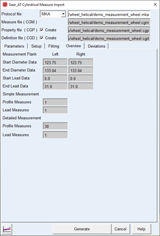
Figure 157 Measure Import - Overview tab
The radial position of measured data points on ideal tooth flank is determined by two parameters. The Start Diameter Data and End Diameter Data define the area on the involute curve, where the given number of measurements is done. Usually, the measurement is equidistant over the Roll Angle, see Figure 158.
Axial position of measured data is determined by two parameters Start Lead Data and End Lead Data, the parameters define where the given amount of measurement is done, usually the measurement is equidistance over the width of the gear.
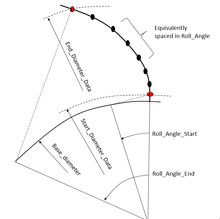
Figure 158 Measurement position on involute
For the options | Do the following |
|---|---|
Start Diameter Data | Diameter where the measurement for each profile is started. Usually it’s close to the Root Form Diameter. |
End Diameter Data | Diameter where the measurement for each profile is ending. Usually is above Tip Diameter. |
Start Lead Data | Axial position where the Lead measured at bottom face on the measured gear started, see Figure 153. |
End Lead Data | Axial position where the Lead measured at the top ace on the measured gear is ending, see Figure 153. |
Profile Measures | Number of measures over profile for Detailed resp. Simple measure type. |
Lead Measures | Number of measures over lead for Detailed resp. Simple measure type. |
Deviations
The measurement deviations are listed on this tab, see (Figure 159).
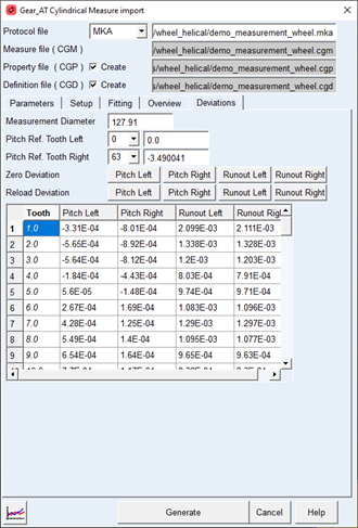
Figure 159 Measure Import - Deviation tab
Run out and Pitch Error should supplement the flank measurement. The data is available for left and right flank separately. This data is stored in created cylindrical property file ( CGP ). The Pitch Error measurement is exercise on Measurement Diameter; the data represent length on arc, see Figure 160. From single pitch error (fp) cumulative pitch error can be calculated (Fp). Cumulative pitch error represents relative position of current and ideal flank position. Usually the Runout is calculated from pitch measurement. Both deviations represent the effect on non-uniform locations on gear wheel, only one of their values should be applied, hence pitch error creates runout and vice versa.
For the options | Do the following |
|---|---|
Measurement Diameter | Diameter on Gear where pitch error is measured |
Pitch Ref. Tooth Left | Select here tooth which is considered as reference one. Offset from this tooth is subtracted from all other teeth values. Usually one tooth has zero cumulative pitch error |
Pitch Ref. Tooth Right | Select here tooth which is considered as reference one. Offset from this tooth is subtracted from all other teeth values. Usually one has zero cumulative pitch error |
Zero Deviations | Set selected error column to zero for all teeth values |
Reload Deviation | Reload selected error column from protocol file for all teeth values |
Tooth | Tooth number |
Ffp_cum Left resp. Right | Cumulative pitch deviation per tooth on Left, resp. Right Flank. Values result from single pitch error measured in micrometers on Measurement Diameter. See Figure 160. |
Fr_sin-Left resp. Right | Single radial deviation per tooth on Left resp. Right Flank. Value results from single pitch error measurement and in most cases have only informative character. See Figure 160. |
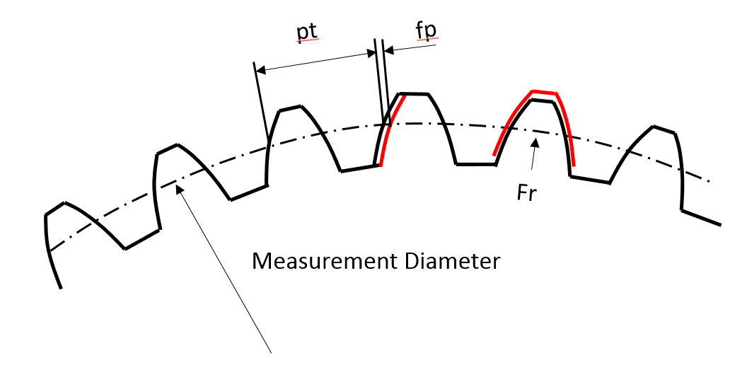
Figure 160 Single Pitch Error and Runout