Requests
The results are reported in element coordinate system (ECS). Each spline element has an element coordinate system (ECS) as shown in Figure 431. The Z-axis of the spline element is identical with the rotation axis. The X-axis and Y-axis lie in the plane normal to the Z-axis at the center of spline element. The Y-axis intersects the spline element at the tooth 1 tip center. The X-axis of the coordinate system follows from the right hand rule.
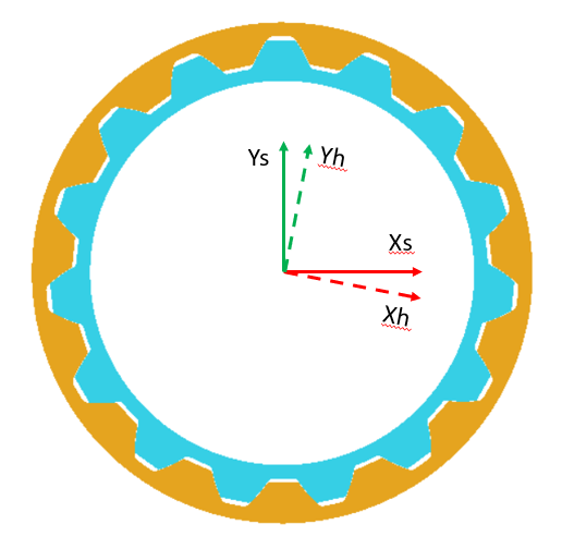
Figure 431 Shaft and Hub spline coordinate systems
There are following request groups and underlying requests for Standard option of the Flexible Tooth:
■Additional_Output_Files
■CGR_Output
■Damping
■FX, FY, FZ_shaft_Viscous
■TX, TY, TZ_shaft_Viscous
■Kinematics
■Distance_Radial_x, y
■Distance_Axial_z
■Misalignment_Lateral
■Misalignment_Radial
■Misalignment_Magnitude
■Relative_TE_Angle
■Relative_TE_ Length
■Total Force and Torque
■FX, FY, FZ_shaft_spl
■TX, TY, TZ_shaft_spl
■FX, FY, FZ_hub_spl
■TX, TY, TZ_hub_spl
There are following request groups and underlying requests for Enhanced option of the Flexible Tooth:
■Additional_Output_Files
■CGR_Output
■Damping
■FX, FY, FZ_shaft_spl_Structure
■TX, TY, TZ_shaft_spl_Structure
■Friction
■FX, FY, FZ_shaft_spl
■TX, TY, TZ_shaft_spl
■Kinematics
■Teeth_in_Contact_Left, Right
■Hub_2_Shaft_rel_WZ
■Hub_2_Shaft_rel_VZ
■Power_Loss
■Friction
■Structural_Damping
■Hydrodynamic_Damping
■Total
■Stiffness
■FX, FY, FZ_shaft_spl
■TX, TY, TZ_shaft_spl
There are following request components for Tooth group of the Flexible Tooth:
■Tooth_1 –> Tooth_n
■Tooth_Force_left, right
■Max_Contact_Pressure_left, right
■Max_Penetration_left, right
■Sliding_Velocity_left, right
■Minimum_Gap_left, right
■Maximum_Squeeze_Velocity_left, right
■Hydrodamping_Force_left, right
■KH_Beta_left, right
■KF_Beta_left, right
■Fm_Friction_left, right
■Tz_Friction_left, right
■Max_Friction_Power_left, right
There are following request components for Teeth group of the Flexible Tooth:
■Teeth_Results_left, right
■Tooth_x_Tooth_Force
■Tooth_x_Max_Contact_Pressure
■Tooth_x_Max_Penetration
■Tooth_x_Sliding_Velocity
■Tooth_x_Minimum_Gap
■Tooth_x_Maximum_Squeeze_Velocity
■Tooth_x_Hydrodamping_Force
■Tooth_x_KH_Beta
■Tooth_x_KF_Beta
■Tooth_x_Fm_Friction
■Tooth_x_Tz_Friction
■Tooth_x_Max_Friction_Power
Extended definition:
The result of Teeth_in_Contact_Left resp. Teeth_in_Contact_Right indicates how many teeth are engaged during operation, due to pitch error and misalignment usually not all teeth are in contact.
The result of Distance_Radial_x, y, Distance_Axial, Misalignment_Lateral, Misalignment_Radial, Misalignment_Magnitude gives the position and the rotation around the X-axis and Y-axis of hub spline relative to shaft spline in shaft spline coordinate system.
The result of Tooth_xx_Max_Penetration helps to evaluate the selected contact stiffness for rigid body contact. In case of a flexible tooth, only a small penetration should be reported under normal operating conditions. See Figure 432 for the definition of the gear teeth numbering convention. Once the tooth is highlighted, the green side marks the left flank, resp. the red side marks the right flank.
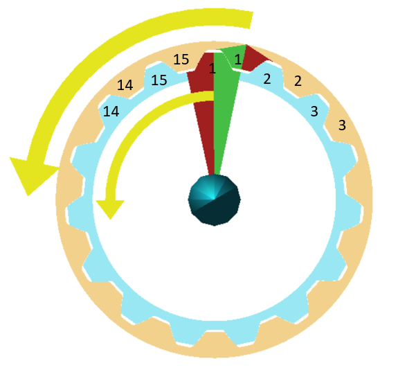
Figure 432 Spline joint - teeth numbering convention
The resulting force and torque vectors are measured in the spline element coordinate system. Force and torques applied on shaft spline are given by FX, FY, FZ_shaft and TX, TY, TZ_shaft. The corresponding force and torque vectors applied on hub spline can be plotted as FX, FY, FZ_hub and TX, TY, TZ_hub. The resulting force and torque vectors including all components from contact, damping and friction are located under the corresponding tooth number group as Tooth_force_left, right.
The tooth specific results can be found under tooth number group. Each tooth can have contact on both flanks, therefore the components in tooth number groups list all values for left and right flanks separately.
Result of relative transmission error (TE) in general expresses the difference between shaft and hub rotations in the spline joint, see Figure 433. The TE value can be calculated in angular units or length units. The TE would be zero for geometrically ideal involute profiles located exactly centric on axis and having rigid spline elements without backlash.
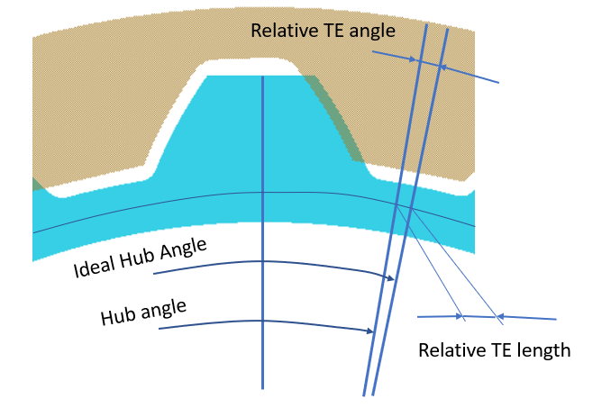
Figure 433 Spline joint - Transmission Error
In case of angular unit, one can express the value as hub spline angle – ideal hub spline angle. The value is calculated for spline elements of a spline joint by Equation (1) and can be found labeled as relative_TE_Angle. Phi means rotation angle. Ideal hub spline angle is identical with shaft spline angle.
 | (1) |
In case of length unit, the value is expressed as length corresponding to base circle arc spanned by relative TE angle and can be found labeled as Relative_TE_Length.
Relative_TE_Length = Relative_TE_Angle * radius_base_shaft_spline