Constant offset test rig
The Gear AT test rig application offers the possibility to analyze specific gear pair contact force and torque in a test rig with a single gear pair extracted from the full model under any combination of constant deviations along five degrees of freedom. The gear wheels are driven by motion in the way that Gear 1 (w1) rotates about Z axis while Gear 2 (w2) perturbates every specified DoF by constant value from nominal configuration of a gear pair in addition to rotation about Z axis complying with the gear ratio. This can be useful for design study of a micro geometry applied to gears.
The window for building or running the testrig can be invoked from menu depicted on Figure 135.
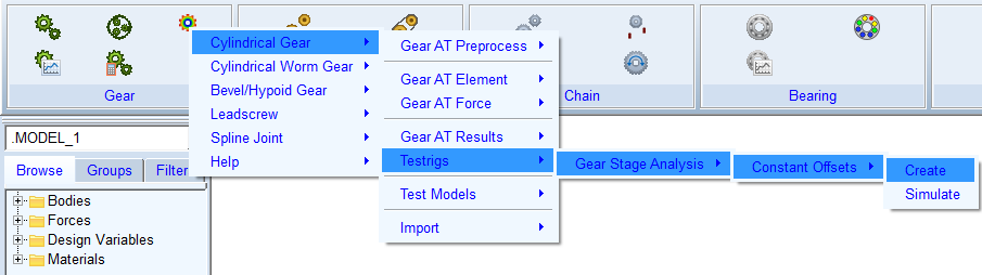
Figure 135 Constant offset testrig launch
The popped up window offers two ways for building the test rig. The process is identical to building test rig for Gear AT Fast preprocessing described in chapter Create Testrig for preprocessing. The fresh created model consists of two gear elements: Gear 1 (w1) and Gear 2 (w2) coupled with contact force initially set to Flex Tooth modeling options. The gear wheels are driven by motions during Adams kinematic simulation. The gears are rotated about its Z axis considering gear pair ratio. The angular position of Gear 2 (w2) is additionally shifted from ideal kinematic position by Rotational offset angle to produce penetration of teeth flanks otherwise separated by backlash. Positive value of the offset angle produces contact on left tooth flank, while negative value contact on right tooth flank.
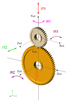
Figure 136 Kinematic test rig degrees of freedom
For analysis of misalignment effects the Gear 2 (w2) can be disturbed from ideal position for all DOF relative to contact coordinate system described in Figure 136. The inputs are entered into window depicted on Figure 137. The fields in calculation options specify simulation parameters. The entry Number of pitches defines rotation angle of Gear 1 as a multiple of Gear 1 pitch angle, while the entry Number of steps/pitch the number of simulation output steps per pitch angle. Pressing button Simulate or Simulate and Save start the analysis and for the second options saves the results to Adams database under name formed from test rig name and entered values of deviation per degree of freedom.
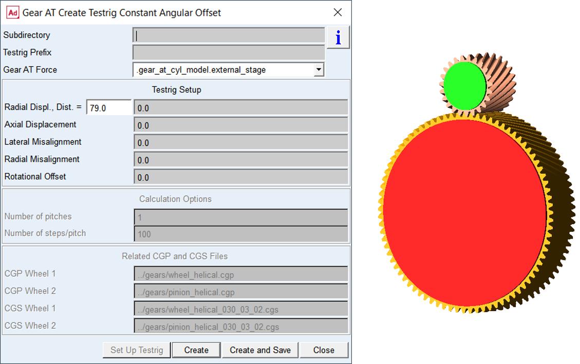
Figure 137 Run constant offset testrig