Analytical
Motor Type
AC Synchronous Motor
An AC synchronous electric motor is a motor in which, at steady state, the rotation of the shaft is synchronized with the frequency of the supply current; the rotation period is exactly equal to an integral number of AC cycles. Synchronous motors contain electromagnets on the stator of the motor that create a magnetic field which rotates in time with the oscillations of the line current. The rotor turns in step with this field, at the same rate.
The motor does not rely on "slip" under usual operating conditions, and as a result produces torque at synchronous speed. The speed of the synchronous motor is determined by the number of magnetic poles and the line frequency.
1. Components
■Rotor: Armature Windings
■Stator: Electromagnets.
2. Types
■Non excited Motors
■Hysteresis Motors
■Permanent Magnet Motors
■Reluctance Motors
■Excited Motors
3. Principle of operation
The operation of a synchronous motor is due to the interaction of the magnetic fields of the stator and the rotor. The stator winding, when excited by a poly-phase (usually 3-phase) supply, creates a rotating magnetic field inside the motor. The rotor locks in with the rotating magnetic field and rotates along with it. Once the rotor locks in with the rotating magnetic field, the motor is said to be in synchronization. A single-phase (or two-phase derived from single phase) stator winding is possible, but in this case the direction of rotation is not defined and the machine may start in either direction unless prevented from doing so by the starting arrangements.
Once the motor is in operation, the speed of the motor is dependent only on the supply frequency. When the motor load is increased beyond the breakdown load, the motor falls out of synchronization and the field winding no longer follows the rotating magnetic field. Since the motor cannot produce (synchronous) torque if it falls out of synchronization, practical synchronous motors have a partial or complete squirrel cage damper (amortisseur) winding to stabilize operation and facilitate starting.
4. Starting methods
Above a certain size, synchronous motors are not self-starting motors. The rotor cannot instantly follow the rotation of the magnetic field of the stator. Since a synchronous motor produces no inherent average torque at standstill, it cannot accelerate to synchronous speed without some supplemental mechanism.
Large motors operating on commercial power frequency include a "squirrel cage" induction winding which provides sufficient torque for acceleration and which also serves to damp oscillations in motor speed in operation. Once the rotor nears the synchronous speed, the field winding is excited, and the motor pulls into synchronization. Very large motor systems may include a "pony" motor that accelerates the unloaded synchronous machine before load is applied.
Polyphase synchronous motors rotate in a direction determined by the sequence of the currents in the phase windings. Single-phase synchronous motors such as in electric wall clocks can freely rotate in either direction unless a shaded-pole type.
5. Applications
■Electric wall clocks
■Synchronous Condensers.
■Centrifugal Machines
■Air Compressors
■Textile mills
■To improve power factor in Large industries
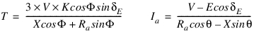
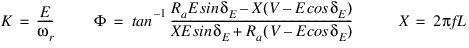
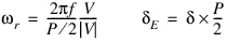
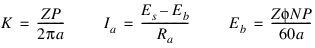
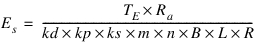
6. Torque Equation
The torque for an AC Synchronous motor is calculated as,
Calculation of K (rated condition),


 for leading =
 for leading =
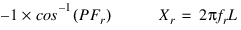
Note: | In actual implementation Er is calculated as magnitude (Er = SQRT( Re(Er)^2 + Im(Er)^2)) and not as complex number. |
Where,
■T = Motor torque
■V = Supply voltage
■K = BEMF constant
■ = Power factor angle
= Power factor angle■ = Electrical Torque angle
= Electrical Torque angle■ = Torque angle
= Torque angle■X = Reactance
■E = Back Emf
■ = Rotor angular velocity
= Rotor angular velocity■f = Supply Frequency
■L = Inductance
■P = Poles
■Er = Rated Back emf
■ = Angular velocity
= Angular velocity■Vr = Rated voltage
■Ir = Rated current
■Ra = Armature resistance
■ = Rated power factor angle
= Rated power factor angle■Xr = Rated reactance
■fr = Rated frequency
■PFr = Rated Power factor
6.1 Torque Angle Calculation ( )
)
)  = Angular displacement of Stator - Angular displacement of rotor
 = Pole pair angle
6.2 Pole Slipping adjustment
Step | Condition | Check | Action | Action Description |
|---|---|---|---|---|
1 | Slip is greater than pole pair angle |  |  | This condition is impractical and introduced for equation syntax (No action). |
2 | Slip is zero |  |  | No action needed. |
3 | Slip is less that pole pair angle |  |  | (Pole pair angle ± Slip),where ± is based on direction of slip |

where:
■P = Poles
■ = Pole Pair angle (Angle between two consecutive North Poles)
= Pole Pair angle (Angle between two consecutive North Poles)6.3 Sample Values
■V = 15 VoltsNs
■f = 150 Hz
■P = 6
■I = 8.4 A
■φ = 0.8
■R = 0.33 ohms
■L = 2 mH
DC Motor
D.C electric motors are mechanically commutated motors. Powered by a D.C electric source, current in the rotor is switched by the commutator. The relative angle between the stator and rotor magnetic flux is maintained near 90°, which generates the maximum torque.
D.C motors have a rotating armature winding but non-rotating armature magnetic field and a static field winding or permanent magnet. Different connections of the field and armature winding provide different inherent speed/torque regulation characteristics. The speed of a D.C motor can be controlled by changing the voltage applied to the armature or by changing the field current. The introduction of variable resistance in the armature circuit or field circuit allowed speed control. Modern D.C motors are often controlled by power electronics systems called D.C drives.
1. Components
■Rotor - Armature Winding
■Stator - Magnets
■Split ring commutator
■Carbon Brushes
2. Principle of operation
The principle of operation of a D.C motor can be stated as 'when a current carrying conductor is placed in a magnetic field; it experiences a mechanical force'. In practical dc motor, field winding produces a required magnetic field while armature conductors play a role of a current carrying conductors and hence armature conductors experience a force.
As conductors are placed in the slots which are on the periphery, the individual force experienced by the conductors acts as a twisting or turning force on the armature which is called Torque. The torque is the product of force and the radius at which this force acts. So overall armature experiences a torque and starts rotating.
In the practical D.C motor, the permanent magnet is replaced by a field winding which produces the required flux called main flux and all the armature conductors, mounted on the periphery of the armature drum, get subjected to the mechanical force. Due to this overall armature experiences a twisting force called torque and armature of the motor starts rotating.
3. Types of D.C Motors
The D.C motors are classified into two depending upon the way of connecting the field winding with the armature winding. The two different types of a D.C motors are shunt motor and series motor.
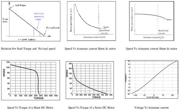
3.1 Shunt D.C Motor
A shunt DC motor connects the armature and field windings in parallel or shunt with a common D.C. power source. This type of motor has good speed regulation even as the load varies, but does not have as high of starting torque as a series DC motor. It is typically used for industrial, adjustable speed applications.
3.2 Series D.C Motor
A series DC motor connects the armature and field windings in series with a common D.C. power source. The motor speed varies as a non-linear function of load torque and armature current. Current is common to both the stator and rotor yielding I2 (current) squared behavior. A series motor has very high starting torque and is commonly used for starting high inertia loads.
4. Applications of a D.C Motor
4.1 Shunt D.C Motor
■Lathes
■Fans
■Pumps
■Band saw
■Drive requiring moderate torques
■Winding/unwinding machines and Tensioners
4.2 Series D.C Motor
■Elevators / hoists
■Dragline Excavators
■Air compressors
■Vacuum cleaners
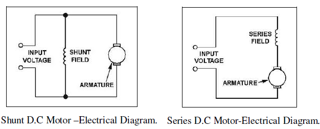
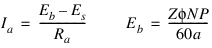
4.3 Torque Equation for D.C Shunt Motor
The torque for a D.C. Shunt motor is calculated as


Where
■T = Torque developed in N-m
■K = Torque constant
■ = Flux per pole in Webers
= Flux per pole in Webers■Ia = Armature current in Amps
■Z = Number of conductors
■P = Number of Poles
■a = Number of parallel paths in the Armature.
■Es = Source Voltage in Volts
■Eb = Back emf induced in Volts
■Ra= Armature resistance in ohms
■N = Revolutions per Minute
4.3.1 Sample values
■ = 25 mwb
= 25 mwb■Z = 200
■P = 4
■a = 2
■Es = 250 Volts
■Ra = 0.7 ohms
■N = 1200 rpm
■K1 = 0.5
4.4 Torque Equation for D.C Series Motor
The torque for a d.c Series motor is calculated as

Where
■T = Torque developed in N-m
■K = Torque constant
■K1 = Series motor constant
■ = Flux per pole in Webers
= Flux per pole in Webers■I = Armature current in Amps
■Z = Number of conductors
■P = Number of Poles
■a = Number of parallel paths in the Armature
■Es = Source Voltage in Volts
■Eb = Back emf induced in Volts
■Ra = Armature resistance in ohms
■N = Revolutions per Minute
4.4.1 Sample values:
■ = 25 mwb
= 25 mwb■Z = 200
■P = 4
■a = 2
■Es = 250 Volts
■Ra = 0.7 ohms
■N = 1200 rpm
5. Typical Characteristic Curves of Shunt and Series D.C Motor
Brushless DC Motor
Brushless DC electric motor also known as electronically commutated motors (ECMs, EC motors) are synchronous motors which are powered by a DC electric source via an integrated inverter/switching power supply, which produces an AC electric signal to drive the motor. Brushless motors may be described as stepper motors; however, the term stepper motor tends to be used for motors that are designed specifically to be operated in a mode where they are frequently stopped with the rotor in a defined angular position.
A typical brushless motor has permanent magnets which rotate and a fixed armature, eliminating problems associated with connecting current to the moving armature. An electronic controller replaces the brush/commutator assembly of the brushed DC motor, which continually switches the phase to the windings to keep the motor turning. The controller performs similar timed power distribution by using a solid-state circuit rather than the brush/commutator system.
Brushless motors offer several advantages over brushed DC motors, including
■More torque per weight and watt
■Increased reliability
■Reduced Noise
■Longer life time
■Elimination of ionizing sparks from commutator
■Overall reduction electromagnetic interference
1. Components
■Rotor - Permanent magnets
■Stator - Armature
■Electronic commutator
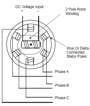
2. Variations in constructions of BLDC Motor
Brushless motors can be constructed in several different physical configurations. In the conventional innerturn configuration, the permanent magnets are part of the rotor, three stator windings surround the rotor.
In outrunner configuration, the radial-relationship between the coils and magnets is reversed. The stator coils form the center (core) of the motor, while the permanent magnets spin within an overhanging rotor which surrounds the core. Outrunners typically have more poles, set up in triplets to maintain the three groups of windings, and have a higher torque at low RPMs.
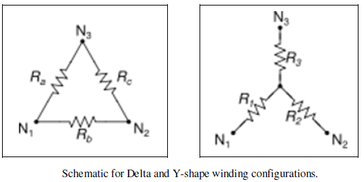
3. Two common electrical winding configurations
3.1 Delta configuration:
The delta configuration connects three windings to each other (series circuits) in a triangle-like circuit, and power is applied at each of the connections. A motor with windings in delta configuration gives low torque at low speed, but can give higher top speed.
3.2 Y-shaped configuration:
The Y-shaped configuration is sometimes called a star winding. It connects all of the windings to a central point (parallel circuits) and power is applied to the remaining end of each winding. Y-configuration gives high torque at low speed, but not as high top speed.
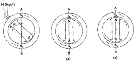
4. Principle of operation
The brushless DC motor is the combination of a permanent excited synchronous motor and a frequency inverter. The inverter has to replace the commutator of a conventional DC motor. Figure below shows how a brushless DC motor can be derived from a mechanically commutated DC motor with three armature slots. Its armature winding corresponds to a three phase winding in delta connection. The commutator acts like a three phase frequency converter. Stator (excitation) and rotor (armature) change places.
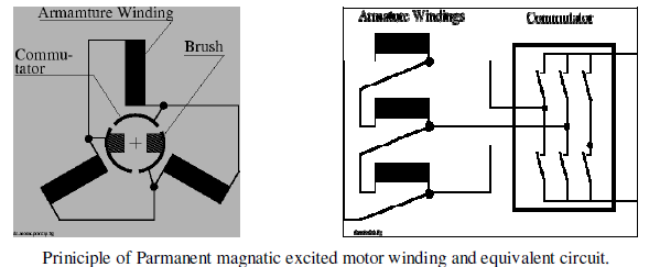
The commutation of a brushless DC motor depends on the position of the rotor. The angle between the magneto-motive forces of stator and rotor is fixed to 90°, so the motor produces maximum torque and needs low reactive current. It might be useful to advance commutation by few degrees to compensate the effects of the stray inductance and minimize reactive current.
5. Applications of BLDC Motor
Brushless DC motors can be used for following two applications:
5.1 Speed control
Brushless DC motors control the speed of the rotor by making use of PID (proportional-integral-derivative) controllers. PID controllers compare the desired speed and actual speed (measured by making use of rotary encoders/tachometers and so on) and calculate current/voltage needed to drive the motor in desired speed.
5.2 Position control
Brushless DC motors control the position (angle) of the rotor with the help of PID controllers. PID controllers compare the desired angle of the rotor and actual angle of the rotor to calculate current/voltage needed to drive the motor in desired angle.
5.3 Examples
■Gyroscope motors
■Biomedical instruments like artificial heart pumps
■Aerospace
■Tape drivers for video recorders
■Actuators for Robots
■Feed drivers for CNC machine tools
■Electric Bicycles
6. Torque Equation for BLDC Motor:
The torque for a BLDC motor is calculated as
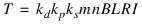
TPID = Pgain x Proportional Input+ Igain x Integral Input + Dgain x Derivative Input
Proportional Input = G x Error
For speed control, Error = Desired Speed-Actual Speed
For position control, Error = Desired Angular Displacement - Actual Angular Displacement
Where
■kd = Distribution Factor
■kp = Coil pitch Factor
■ks = Slot Skew Factor
■m = Number of Teeth per phase
■n = Number of Turns per phase
■B = Strength of the permanent Magnetic field
■L = Length of rotor windings
■R = Radius of Armature
■I = Current in the Motor winding
■T = Torque developed in N-m
■φ = Flux per pole in Webers
■Z = Number of conductors
■P = Number of Poles
■a = Number of parallel paths in the Armature
■Es = Source Voltage in Volts
■Eb = Back emf induced in Volts
■Ra = Armature resistance in ohms
■N = Revolutions per Minute
■TE = minimum value of TPID & Trated
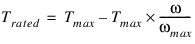
■Trated = Rated Torque
■Proportional Input =Error from difference between actual and desired speed (or angle) of the rotor
■Integral Input = Integral of Proportional Input
■Derivative Input = Derivative of Proportional Input
■G = Gain applied to the error
■Pgain = Gain applied to the Proportional Input
■Igain = Gain applied to the Integral Input
■Dgain = Gain applied to the Derivative Input
■Tmax = Maximum Torque
■ max = Maximum Angular Velocity
max = Maximum Angular Velocity■ = Actual Angular Velocity of the rotor
= Actual Angular Velocity of the rotorImportant: | In actual implementation Ia is taken as (Es-Eb)/Ra as modelling implementation needs Ia to be positive and motor will rotate only if Es > Eb, negative value of current in basic equation denotes direction of the current flow. |
6.1 Sample Values
■kd = 0.966
■kp = 0.866
■ks =1
■n = 120
■B = 1.3
■L = 25 mm
■R = 43 mm
■Pgain = 1.0e-3
■Igain = 2.0e-2
■Dgain = 4.0
■G = 10.0
■Tmax = 150.0e+3 N-mm
■ max = 500 deg/s
max = 500 deg/sStepper Motor
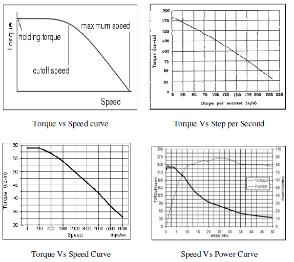
A stepper motor is a brushless, synchronous electric motor that converts digital pulses into mechanical shaft rotation. Every revolution of the stepper motor is divided into a discrete number of steps and the motor must be sent a separate pulse for each step. Stepper motors provide a means for precise positioning and speed control without the use of feedback sensors. Stepper motors are very popular in digital control circuits, such as robotics, because they are ideally suited for receiving digital pulses for step control. Each step causes the shaft to rotate a certain number of degrees.
1. Components of Stepper Motor
■Rotor: Multi-Toothed Permanent Magnet.
■Stator: Field Windings.
2. Types of Stepper Motors
The main types of Stepper motor are.
■Variable Reluctance Stepper.
■Permanent Magnet Stepper.
■Hybrid Synchronous.
3. Principle of operation
The basic operation of a stepper motor allows the shaft to move a precise number of degrees each time a pulse of electricity is sent to the motor. Since the shaft of the motor moves only the number of degrees that it was designed for when each pulse is delivered, the pulse can be controlled for the positioning and speed.
The rotor of the motor produces torque from the interaction between the magnetic field in the stator and rotor. The strength of the magnetic fields is proportional to the amount of current sent to the stator and the number of turns in the windings.
The stepper motor uses the theory of operation for magnets to make the motor shaft turn a precise distance when a pulse of electricity is provided.
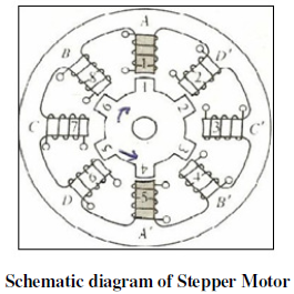
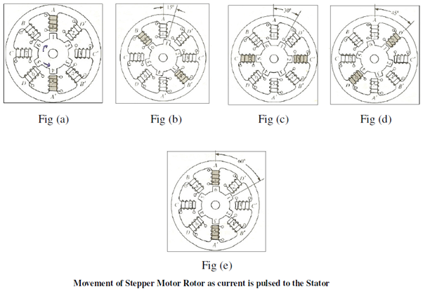
Above Figure shows a typical cross-sectional view of the rotor and stator of a stepper motor. From the diagram it can be seen that the stator (stationary winding) has eight poles, and the rotor has six poles (three complete magnets). The rotor will require 24 pulses of electricity to move the 24 steps to make one complete revolution. Another way to say this is that the rotor will move precisely 15° for each pulse of electricity that the motor receives. The number of degrees the rotor will turn when a pulse of electricity is delivered to the motor can be calculated by dividing the number of degrees in one revolution of the shaft (360°) by the number of poles (north and south) in the rotor. In this stepper motor 360° is divided by 24 to get 15°. When no power is applied to the motor, the residual magnetism in the rotor magnets will cause the rotor to detent or align one set of its magnetic poles with the magnetic poles of one of the stator magnets. When the rotor is in a detent position, it will have enough magnetic force to keep the shaft from moving to the next position.
When power is applied, it is directed to only one of the stator pairs of windings, which will cause that winding pair to become a magnet. One of the coils for the pair will become the North Pole, and the other will become the South Pole.
4. Applications
■Linear actuators
■Goniometry
■Floppy disk drives
■Flatbed scanners
■Computer printers & plotters
■Intelligent lighting
5. Torque Equation for Stepper Motor:
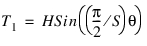
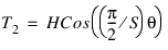
The torque for a Stepper motor is calculated as,
Where
■T1 = Torque on the first winding.
■T2 = Torque on the Secondary winding.
■H = Holding Torque in N-m.
■S = Step Angle in radians.
■θ = Shaft Angle in radians.
Notes: | Stepper Motor can be controlled in the following two ways: ■One Phase on - Full Step Drive: Torque on the first winding (T1) is alone considered. ■Two Phase on - Full Step Drive: Torque on the first winding (T1) and torque on the second winding (T2) are considered. |
5.1 Shaft Angle ( ) calculation
) calculationShaft angle  = Detent Angle - Actual Angular Displacement
= Detent Angle - Actual Angular DisplacementThe shaft angle ( ) is calculated based on the input type:
) is calculated based on the input type:■PPS Vs time
■Target Angle Vs time
Detent Angle = Detent Count x S
Detent Count = Number of detent positions as obtained from the PPS Vs Time or Target angle Vs Time Curve.
S = Step Angle in radians.
5.2 Sample Values:
■H = 100 N-m
■ = 0.5 radians
= 0.5 radians6. Typical Characteristic curves for a Stepper Motor