Preprocess Needle Bearing Contact
Machinery → Bearing AT → Needle Bearing → Preprocessing → Contact
The Needle Contact file Write dialog box allows you to create needle bearing contact file by running Bearing AT contact pre-processor.
Main
For the options | Do the following |
|---|---|
Needle Property File | Select existing needle property file (*.npf) |
Microgeometry Modif. Name | Enter suffix for contact file name. The contact file name of the bearing is composed by property file base name appended by the character string of the Microgeometry Modif Name field. The length of the character string is limited to 20 characters. |
mport *.rcf | Click to import existing bearing contact file to populate all fields of the dialog box. |
Contact
The compliances of the rolling element against the ring are computed by a high-performance contact algorithm. The user needs to define workspace of rolling element against ring, which is stored in the needle bearing contact file (*.ncf). A *.log file provides information about contact processing.
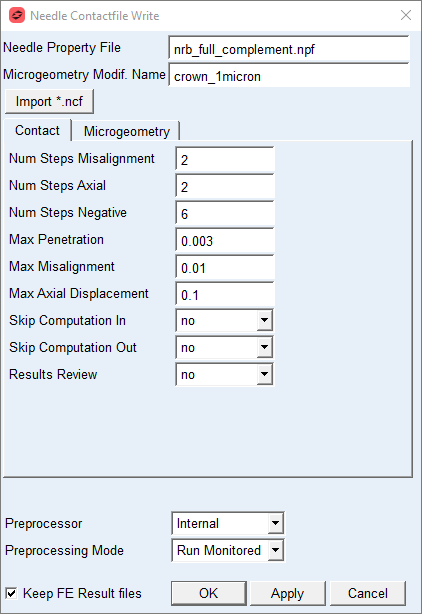
Figure 91 Contact dialog box – Contact tab
For the options | Do the following |
|---|---|
Num Steps Misalignment | Enter number of steps for misalignment. The term Misalignment refers to the relative rotation of the roller against the race, see Figure 92 and Figure 95. The roller is oriented from negative (-) Max_misalignment to positive (+) Max_misalignment with increment of Δβ= Max_misalignment / Num Steps Misalignment Effectively there are total number of steps applied from negative Max_misalignment to positive Max_misalignment defined by the formula: Steps total = 2 * Num Steps Misalignment +1 Default = 2 |
Num Steps Axial | Enter the number of steps the needle is moved in axial direction wrt. inner ring from -Max. Axial Displacement to zero axial displacement and from zero axial displacement to +Max. Axial Displacement by increment of Δd= Max_axial_displacement / Num Steps Axial as depicted on Figure 94 Default = 2 |
Num Steps Negative | Enter the number of penetration steps in negative direction. The value should be multiple of 2. The roller load is zero in design position in case of absence of clearance and misalignment. Any misalignment will generate a load which should be relieved by moving roller away from the race, thus ensure the point of first load transfer is robustly identified, see Figure 92 and Figure 95. Default = 6 |
Max Penetration | Enter the maximum penetration of roller vs. inner ring and roller vs. outer ring, see Figure 93 andFigure 96. The Max Penetration is applied in 20 penetration steps. Default = 0.003 |
Max Misalignment | Enter value of roller maximum angular misalignment. The term Misalignment refers to the relative rotation of the roller against the race, see Figure 92 and Figure 95. The input value (in degrees) is usually a small number and is identical for the inner and outer race for the determination of the compliance. Default = 0.01 |
Max Axial Displacement | Enter the maximum axial displacement amplitude of the roller vs. inner ring along inner ring Z axis. See Figure 94. Default = 0.1 |
Skip Computation In | Set to Yes to skip execution of contact simulation for the roller vs. inner ring. It might save some time in case you need to redo contact simulation of the outer ring only. Default = no |
Skip Computation Out | Set to Yes to skip execution of contact simulation for the roller vs. outer ring. It might save some time in case you need to redo contact simulation of the inner ring only. Default = no |
Results Review | Set to one of following options: ■yes: to output some additional *.rre result files with contact pressure table and Nastran cards for further postprocessing ■no: to not output additional result files Default = no |
Mode to run Preprocessing | Select one of following options for running contact preprocessor. ■Run Quiet: executes contact preprocessing without any output to the screen but to the *.log file in the working directory ■Run Monitored: executes contact preprocessing with output to the screen and to the *.log file in the working directory ■Files Only: the batch file is created but not submitted to execution, one has to launch it manually (not available on linux). Default = Run Monitored |
Keep FE Results files | If you want to keep the results files from Nastran (*.pch) to run another contact simulation, select Keep FE Results files in the toggle button otherwise those will be removed after contact simulation is completed successfully. Default = ON |
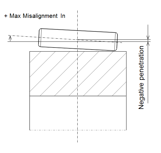
Figure 92 Max. misalignment of needle vs. inner ring
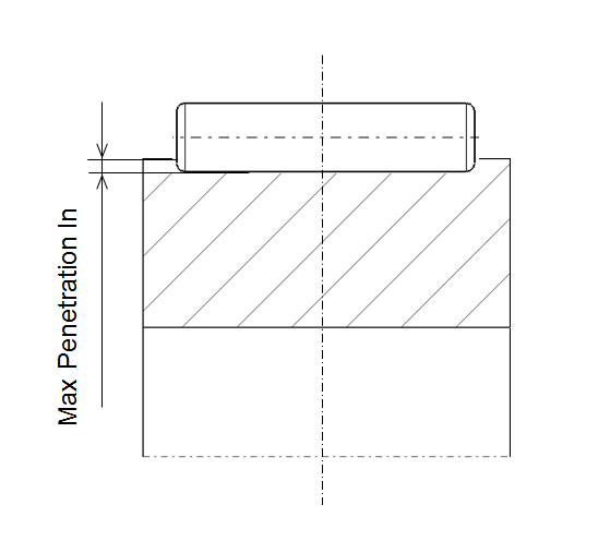
Figure 93 Max. penetration of needle vs. inner ring
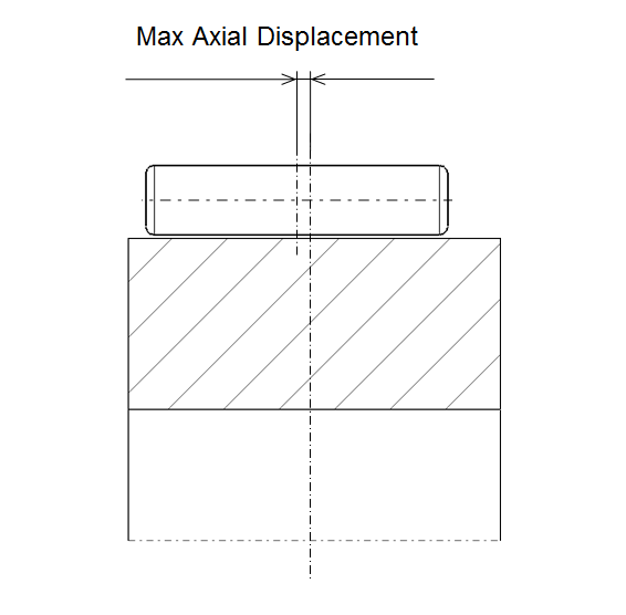
Figure 94 Max. axial displacement of needle vs. inner ring
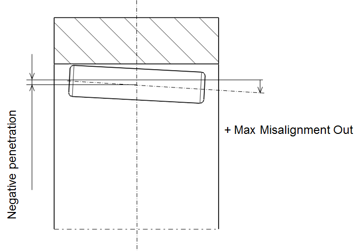
Figure 95 Max. misalignment of needle vs. outer ring
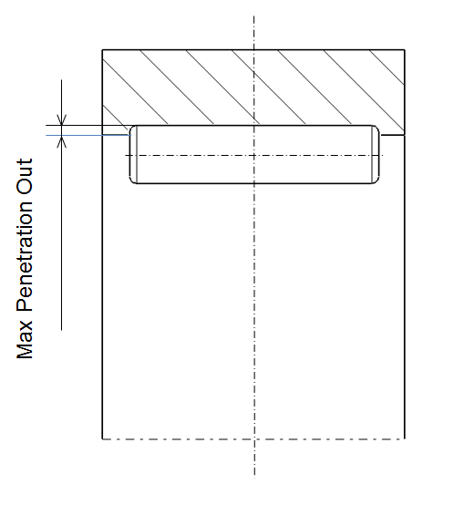
Figure 96 Max. penetration of needle vs. outer ring
Microgeometry
It is assumed in Bearing AT, that micro-geometry has only effects of second order on the flexibility of the roller. This assumption allows investigating the effect of any micro-geometry without re-computation of the finite element models, what helps to save CPU-time and gives you more flexibility in modeling.
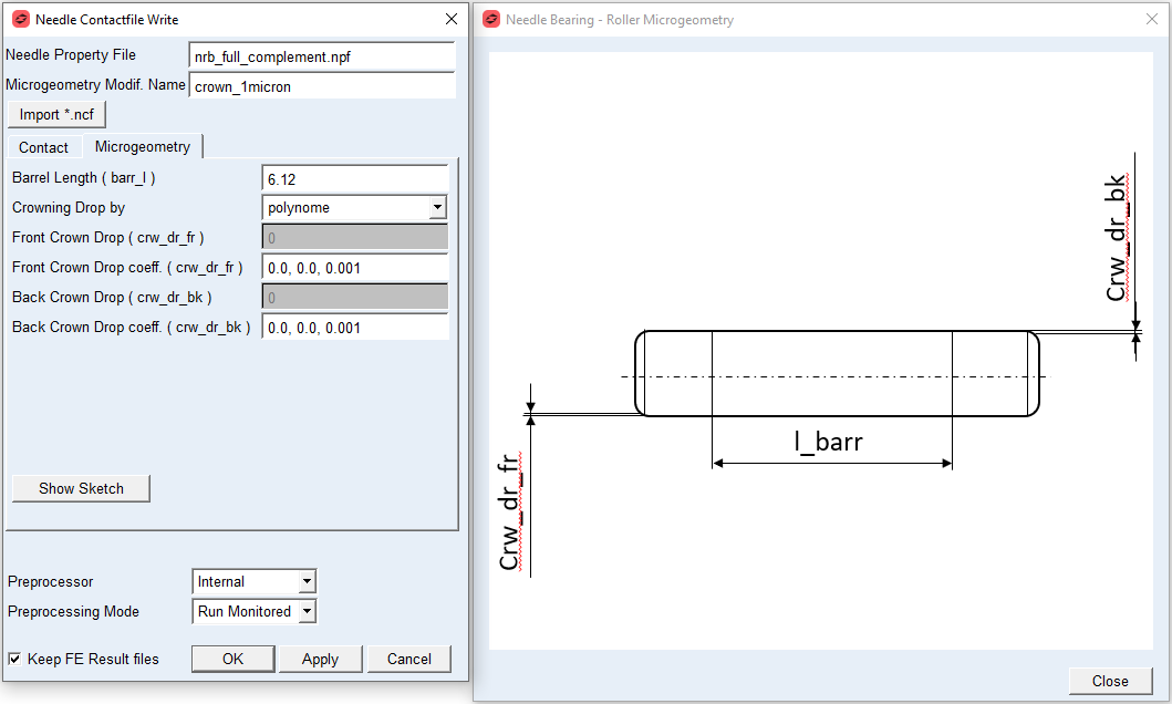
Figure 97 Contact dialog box – Microgeometry tab
For the options | Do the following |
|---|---|
Barrel Length (barr_l) | Enter value of barrel length. The barrel length is the length of the roller, where it has the unmodified surface. The barrel length is measured along the Z - axis of the bearing and it is symmetrically distributed on both sides of the roller. Default = 0.5 * Length_of_Needle |
Crowning Drop by | Select one of following options to define crowing drop: ■arc - is tangent to the roller surface at barrel length; requires input of the drop only ■polynome - is of 3-rd order defined by an independent variable u, which has the value of zero at barrel length and a value of 1 at the fillet (see Figure 98) Default: polynome |
For the option Crowning Drop by the Arc: | |
Front Crown Drop (crw_dr_fr) | Enter value of crowning drop on front side (Z neg of bearing reference marker) of roller in model length units. The crowning profile is of circular shape. |
Back Crown Drop (crw_dr_bk) | Enter value of crowning drop on back side (Z pos of bearing reference marker) of roller in model length units. The crowning profile is of circular shape. |
For the option Crowning Drop by the Polynome: | |
Front Crown Drop coeff. (crw_dr_fr) | Enter value of crowning drop coefficients on front side (Z neg of bearing reference marker) of roller in model length units. The polynomial coefficients a1 , a2 , a3 define Front Crowning Drop curve by following polynomial equation: crw_dr_fr = a1 * u + a2 * u**2 + a3 * u**3 For instance, enter ‘0.0, 0.0, 0.001’ to get crowning drop of 0.001 of cubic shape. Default: 0.0, 0.0, 0.001 |
Back Crown Drop coeff. (crw_dr_bk) | Enter values of crowning drop coefficients on back side (Z pos of bearing reference marker) of roller in model length units. Enter polynomial coefficients a1 , a2 , a3 which define Back Crowning Drop curve by following polynomial equation: crw_dr_bk = a1 * u + a2 * u**2 + a3 * u**3 For instance, enter ‘0.0, 0.001, 0.0’ to get crowning drop of 0.001 of quadratic shape. Default: 0.0, 0.0, 0.001 |
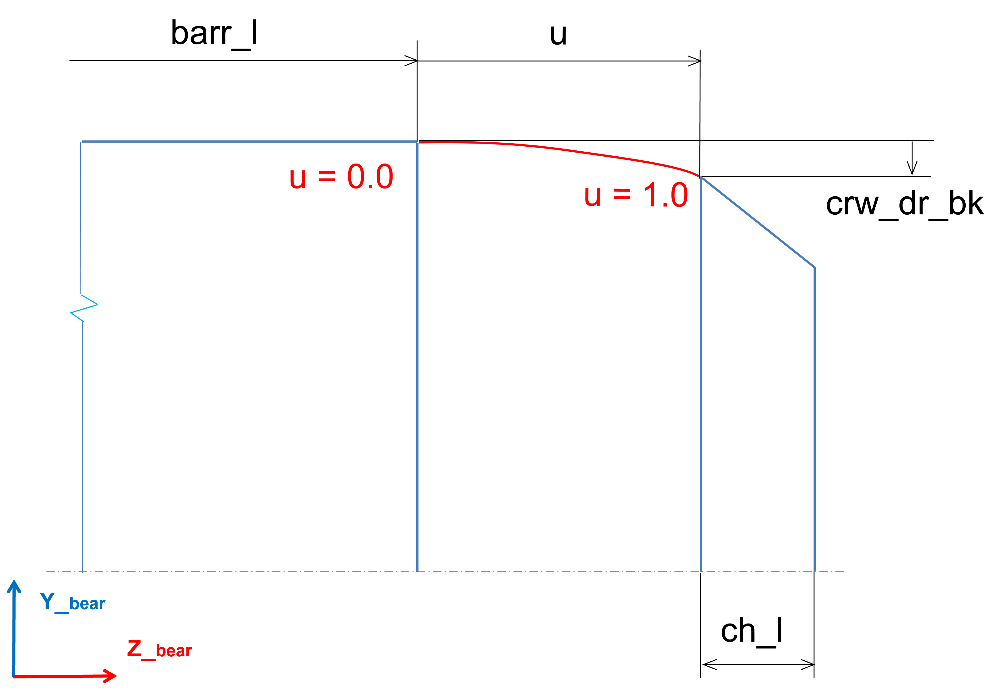
Figure 98 Needle crowing drop