Preprocess Tapered Bearing Roller Contact
Machinery → Bearing AT → Tapered Roller Bearing → Preprocessing → Contact
The write contact file dialog box allows you to create tapered roller bearing contact file by running Bearing AT contact pre-processor.
For more detailed information about the process, please read Bearing AT manual.
Main
For the options | Do the following |
|---|---|
Tapered Roller Property File | Select existing tapered roller bearing property file (*.tpf). |
Microgeometry Modif. Name | Enter suffix for filename The contact file name of the bearing is appended by the character string Microgeometry Modif Name. The length of the character string is limited to 20 characters. |
Import *.tcf | Click to import existing bearing contact property file |
Contact
The compliances of the rolling element against the ring are computed by a high-performance contact algorithm. The user needs to define workspace of rolling element against ring, which is stored in the tapered roller bearing contact file for the inner race (*_in.tcf) and the outer race (*_out.tcf). A *.log file provides information about contact processing.
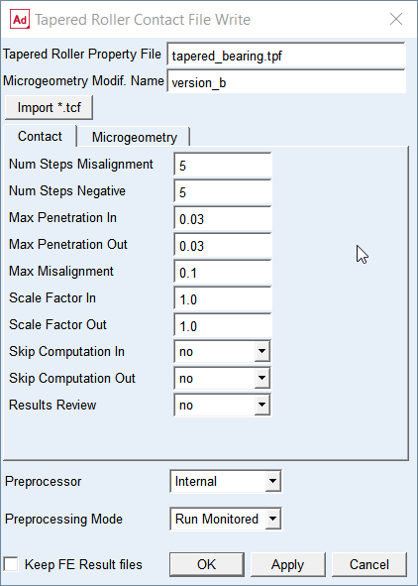
Figure 61 Input data for taper roller bearing contact analysis
For the options | Do the following |
|---|---|
Num Steps Misalignment | Enter number of steps for misalignment The term Misalignment refers to the relative rotation of the roller against the race. The right hand rule applies with respect to the bearing coordinate system. The roller is oriented from -Max_misalignment to +Max_misalignment in a number of steps defined by this input parameter. Default = 5 |
Num Steps Negative | Enter the number of penetration steps in negative direction. The roller load is zero in design position in case of absence of clearance and of misalignment. Any misalignment will generate a load which should be relieved by moving roller away from the race, thus ensure the point of first load transfer is robustly identified. Default = 5 |
Max Penetration In | Enter value of maximum penetration of roller vs. cone race surface (inner ring) The roller is pushed into the inner ring by this value in 20 steps. The roller moves along the normal to the pitch cone (Figure 63). Default = 0.03 |
Max Penetration Out | Enter value of maximum penetration of roller vs. cup race surface (outer ring) The roller is pushed into the outer ring by this value in 20 steps. The roller moves along the normal to the pitch cone (Figure 63). Default = 0.03 |
Max Misalignment | Enter value of roller maximum angular misalignment The term Misalignment refers to the relative rotation of the roller against the race. The right hand rule applies wrt. the bearing coordinate system. The input value (in degrees) is usually a small number and is identical for the inner and outer race for the determination of the compliance (Figure 62). Default = 0.1 |
Scale Factor In | Enter the scale factor to adjust results of contact analysis for the roller vs. inner ring. Default = 1.0 |
Scale Factor Out | Enter the scale factor to adjust results of contact analysis for the roller vs. outer ring. Default = 1.0 |
Skip Computation In | Set to Yes to skip execution of contact simulation for the roller vs. inner ring. It might save some time in case you need to redo contact simulation of the outer ring only. Default = no |
Skip Computation Out | Set to Yes to skip execution of contact simulation for the roller vs. outer ring. It might save some time in case you need to redo contact simulation of the inner ring only. Default = no |
Mode to run Preprocessing | Select one of following options for running contact pre-processor. ■Run Quiet: executes contact preprocessing without any output to the screen but to the *.log file in the working directory ■Run Monitored: executes contact preprocessing with output to the screen and to the *.log file in the working directory ■Files Only: the batch file is created but not submitted to execution, one has to launch it manually |
Results Review | Set to one of following options: ■yes: to output some additional *.tre result files with contact pressure table and Nastran cards for further postprocessing ■no: to not output additional result files Default = no |
Keep FE Results files | If you want to keep the results files from Nastran (*.pch) to run another contact simulation, select Keep FE Results files in the toggle button |
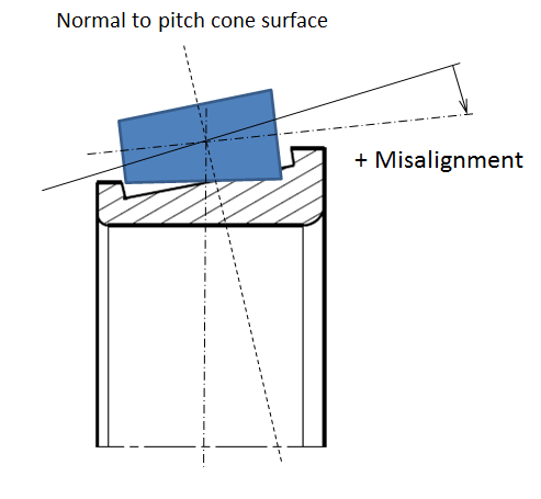
Figure 62 Max. misalignment or roller vs. inner ring
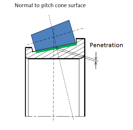
Figure 63 Max. penetration of roller vs. inner ring
Microgeometry
It is assumed in Bearing AT, that micro-geometry has only effects of second order on the flexibility of the roller. This assumption allows investigating the effect of any micro-geometry without re-computation of the finite element models, what helps to save CPU-time and gives you more flexibility in modeling.
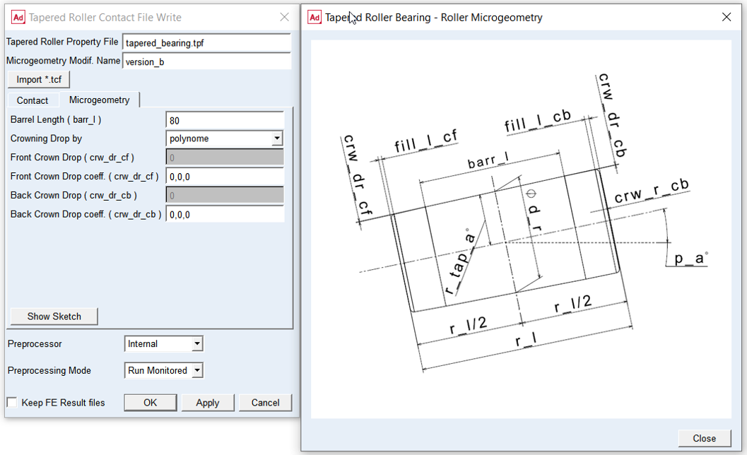
Figure 64 Roller microgeometry
For the options | Do the following |
|---|---|
Barrel Length ( barr_l ) | Enter value of barrel length The barrel length is the length of the cone, where it has the unmodified surface. The barrel length is measured along the Z -axis of the bearing and it is equally distributed on both sides of the roller. Default = no |
Crowning Drop by | Select one of following options to define crowing drop: ■arc - is tangent to the roller surface at barrel length; requires input of the drop only ■polynome - is of 3-rd order defined by an independent variable u, which has the value of zero at barrel length and a value of 1 at the fillet (Figure 65). |
Front Crown. Drop ( crw_dr_cf ) | Enter value of front crowning drop. This input is active only when arc option is selected for Crowning Drop by menu. |
Front Crown. Drop Coefficients ( crw_dr_cf ) | Enter values of front crowning drop coefficients. This input is active only when polynome option is selected for Crowning Drop by menu. Enter polynomial coefficients a1 , a2 , a3 which define Front Crowning Drop curve by following polynomial equation: crw_dr_cf = a1 * u + a2 * u**2 + a3 * u**3 For instance, enter ‘0.0, 0.5, 0.0’ to get crowning drop of 0.5 of quadratic shape |
Back Crown. Drop ( crw_dr_cb ) | Enter value of back crowning drop. This input is active only when arc option is selected for Crowning Drop by menu. |
Back Crown. Drop Coefficients ( crw_dr_cb ) | Enter values of back crowning coefficients. This input is active only when polynome option is selected for Crowning Drop by menu. Enter polynomial coefficients a1 , a2 , a3 which define Back Crowning Drop curve by following polynomial equation: crw_dr_cb = a1 * u + a2 * u**2 + a3 * u**3 For instance, enter ‘0.0, 0.5, 0.0’ to get crowning drop of 0.5 of quadratic shape. |
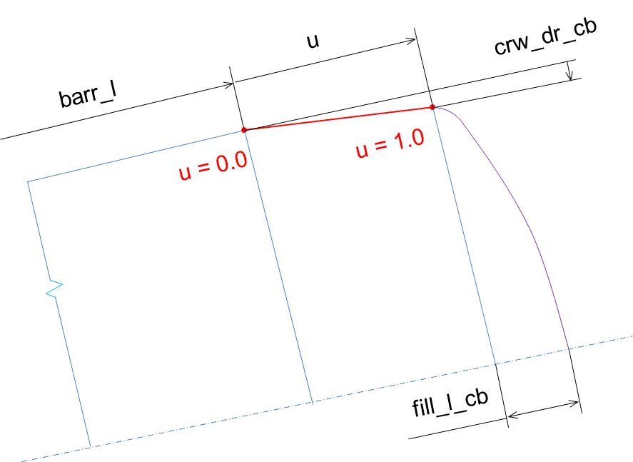
Figure 65 Roller crowing drop