Working with Adams Mechatronics
Working with Components
What you can do in the Adams Car Template Builder and in Adams View is:
■Create, modify, rename and delete transducer signals and actuator signals
■Create, modify, rename and delete control systems
■Modify, rename, rearrange and delete the auto-generated control system inputs/outputs
Please note that there is no dialog box available to create a control system input/output object; however, they can be modified by using Modify dialog box.
In contrast to Adams Car Template Builder and Adams View, you are only allowed to modify the components in the Adams Car Standard Interface mode, i.e., modify different signals and the control systems.
Transducer Signals
The following picture shows how to create a transducer signal which should measure a state in the mechanical system. This menu is available in Adams Car Template Builder and in Adams View.
Note that in Adams Car case, the transducer signal should be created in the template where the signal arises.
The menu choice above will display the following dialog box:
Among other inputs such as name and type (only valid for Adams Car), you should enter a function expression that is measuring a state of the mechanical system. Note that you can alternatively consider the function definition as a user routine subroutine. For more help on this please refer to Create/Modify Transducer/Actuator or Control System Input/Output dialog box help.
As for all type of signals in Adams Mechatronics in addition to choosing the applicable unit type and unit string, you also have the possibility to scale the function and apply a disturbance and/or delay. The later options are described more in detail here.
Further, you also have the option to turn on/off the auto-created signal request and measure. The request and the measure can be expressed in model unit and, if the unit string differs from the model units, also in the user specified signal unit. In the following example, the signal can be easily plotted in the Adams Postprocessor in model units "deg/second" (in this case "degrees" and "second" are angle and time model units, respectively) and also in "rpm" (in this case it is assumed that the function expression is producing result in "rpm").
A transducer signal activity can be set in two different ways:
■Always: the transducer signal object is always active in your model
■Only if connected: the transducer object is inactive until it gets connected to a corresponding control system input. If it is not connected, it will stay inactive, and will not be visible to the solver (i.e. not visible in the .adm file)
To understand more about how to use the activity setting, please refer to Activity settings section. More details about the dialog settings can be found in the dialog box help (F1- help).
Last, by selecting the push button shown in following picture, you will get the option to select entities located in the model that should be activated/deactivated dependent on if the signal gets connected or not. Please refer to Activity settings to learn about this feature.
In Adams Car Standard Interface mode, the function expression cannot be edited as expected. But other options like request/measure activity, scale factor, disturbance, delay and unit information can still be modified. These choices are then stored in the subsystem file.
In Adams View all dialog box options above are available except the possibility to create symmetric signals. Hence, all signals in Adams View are of ‘single’ type.
Actuator Signals
The actuator signal is used to transfer the output from the control system to the mechanical system and is created via the menu below. In Adams Car the signal should be created in the template where the signal is used and referred to.
The dialog box of creating a new actuator signal is similar to one for the transducer signal except for the function expression which is deactivated. The reason is that the actuator signal gets its value from a control system output and hence the function expression is already defined and cannot therefore be changed.
The available activity settings for an actuator signal are:
■Always: the actuator signal object is always active in your model
■Only if connected: the actuator object is inactive until it gets connected to a corresponding control system output. If it is not connected, it will stay inactive, and will not be visible to the solver (i.e. not visible in the .adm file)
■Only if referred to: If another object is using the actuator signal in a function expression, the actuator signal will be active. A typical example is if you have a force using the actuator signal in its expression.
The user has the option – as for the transducer signal – to select entities whose activities depends on if the actuator signal gets connected or not. To understand more about how to use the activity setting together with the options to select activity dependent objects, please read Activity settings.
Control Systems
To create a control system, please use the menu below.
Dialog box below will be displayed and more detailed information about each option menu and field can be found in the Create/Modify Control System dialog box help.
In this dialog box, you specify control system Name, Type (only in Adams Car), System Type and Number of Inputs/Outputs.
The System Types can be one of the three following types:
■Function Expression - use the function builder to create a controller based on Adams entities
■Co-simulation - run co-simulation between Adams and a controls package (Easy5 or MATLAB/Simulink)
■External System Library (ESL) - use an external system library (i.e dynamic link library) that has been exported from Easy5 or MATLAB/Code Generation. An ESL Property File refers to an ESL (also known as dynamic link library) file.
If the System type Function Expression is chosen, no property file or other additional input is needed, see below. The function expression of the controller is instead defined and saved in each control system output. In Adams Car the function expression for each control system output is defined in the Template Builder mode, however, you are able to modify the control signal output expression using Create/Modify Control System dialog box.
If the System type Co-simulation is chosen, then you need to select the Control Package software you want to use and if Initial Static Analysis should be performed or not. The selected co-simulation settings will be used by default when exporting the plant using Adams Mechatronics Export Plant for Co-simulation /Setting up ESL dialog box.
If the System type External System Library is selected, then you need to select the External System Library file and whether Static Hold should be on or off, which determines if Adams Solver should keep the initial value of the control signal constant during static analysis.
By selecting the push button shown in following picture, you can open the Control Signal Editor dialog box, where you enter Signal Name (port name), Unit type and Unit string and Scale factor for each input and output of the control system. Typically that information is received from the supplier of the control system.

Control System Inputs
When you create a control system, you specify the number of control system inputs and thereby control system inputs are auto-created. After creation, you can – as for all types of signals- modify the unit type, unit string, delay, disturbance, etc of control system inputs using Create/Modify Control System dialog box. Using the Signal Manager, you can hook up the appropriate transducer signal to the corresponding Control System Input.
Control System Outputs
When you create a control system, you also specify the number of control system outputs and thereby they are auto-created directly. After creation, you can modify the unit type, unit string, delay, disturbance, etc of control system outputs using Create/Modify Control System dialog box. Using the Signal Manager, you can hook up the appropriate Control System Output to the corresponding actuator signal.
Naming conventions
In Adams Mechatronics names of the control system and the different signals conform to the following conventions:
Transducer Signal: ues_cst_’signal name’ (cst = Control Signal Transducer)
Actator Signal: ues_csa_’signal name’ (csa = Control Signal Actuator)
Control System: ues_’system name’
Control System Input: ues_csi_’system name’_’input port name’ (csi = Control System Input)
Control System Output: ues_cso_’system name’_’output port name’ (cso = Control System Output)
Here ‘ues’ stands for ‘user-defined entity single’. In Adams Car it is possible to create symmetric signals and control systems. In that cases the prefixes for the symmetric (left/right) signals are uel_cst_’signal name’ and uer_cst_’signal name’ (for a transducer signal)
Signal Manager
The Signal Manager is the key feature of Adams Mechatronics and is where all connections are set, i.e., the connection between the control systems and transducer/actuator signals of the mechanical system. The following schematic illustrates the signal flow in Adams Mechatronics.
While an overview of Signal Manager is presented here, a more detailed description can be found in the Adams Mechatronics Tutorials.
To open Signal Manager, use the following menu. Note that in Adams Car this menu is only available in Standard Interface Mode.
Select the assembly (Adams Car) or model (Adams View) in which the control system exists.
As an example from the information in the preceding dialog box, you can notice that there are two control systems in the assembly and they are located in the two subsystems with major roles 'control system' and the minor roles are 'ABS' and 'ESP'.
Note that, alternatively, the control systems could have been created in the one single template/subsystem. In that case, both control systems would have the same major and minor roles.
In Adams View, as there is no major and minor role concept; the major/minor role columns are hided.
By selecting a control system in the dialog box above (you select by double clicking on any cell in the row of the corresponding control system), a new dialog box pops up which gives an overview of the connectivity for each input and output port of the control system (following picture). The information in the gray area (input port name and unit type) is related to the control system itself - and therefore cannot be changed here - while the white area is a 'selectable' area.
You also get the information (from the major and minor role) that in which subsystem the connected signal is located. The name convention of the signals also reveals the type of connected signal. For instance input port number 8 with port name 'wheel_speed_fl' below is connected to a ('uel_cst') left side transducer signal named as 'wheel_speed_front'.
By selecting an input port row in the white area, you will have the possibility to choose a signal from the Available Signal List in ‘Selecting input’ dialog box to connect to the certain input port. Please note that only the signals of the same unit type as the input port are displayed in the (available signal) list. In the example below, only the transducer signals and control system outputs of ‘angular velocity’ unit type are shown in the table as possible candidates to be connected to the ‘wheel_speed_fl’ input port.
The output tab, as depicted in following picture, is quite similar to input tab except that here the gray area (information related to the control system; i.e., output port name and unit type) is located on the left side of the table (to resemble the signal flow) and also that more then one signal can be connected to the output port.
In the following lines, some background or implementation information is presented which may be of interest to advanced users.
■Note that each signal connection is based on following Connector data
■Signal Name
■Side (left/right/single)
■Major Role
■Minor Role
Once connections have been established, each individual connection is saved into a connector data section of the signal component.
■Connector info is only stored with control system inputs and actuator signals since these can only be connected to only one single signal in contrast with transducer signals and control system outputs which may be connected to more than one signal
■The use of major and minor role makes the connector info independent of assembly and subsystem name. It is then possible to swap control systems or subsystems without need of redoing the connecting process in signal manager
■The connector concept is comparable with input communicator in standard Adams Car. One difference is though while you work with communicators in the template builder mode, here you setup the connections on the assembled model in the Standard Interface Mode
■In the Adams View, only the connector signal name is used when making connections
Units in Adams Mechatronics
Adams Mechatronics supports arbitrary units in all signal types. It also takes care of units conversion, for example, from a transducer signal to the corresponding input signal in the control system. The units are handled by two attributes in Adams Mechatronics: unit type and unit string.
Unit type indicates which kind of unit you are using, for example, velocity or torque. Adams Mechatronics only allows connection of the same unit types when assigning a transducer signal to a control system input, a control system output to an actuator signal, or a control system output to input of another control system.
The unit string is used by Adams Mechatronics to calculate the appropriate conversion factor. For example, if you define the wheel speed transducer signal to send signal in mm/s unit and your control system input requires a km/h unit, the conversion is performed by Adams Mechatronics. This means that a unit conversion occurs automatically if the units are not the same, for example, for a transducer signal and the corresponding control system input.
There is a set of pre-defined unit types and unit strings available in Adams Mechatronics. However, if your control system is working with other type of unit, you can create your own unit. See the table below for more information about how to choose different unit type and unit string alternatives.
Unit type | Unit String | Used when | Comment |
|---|---|---|---|
length, angle, ... | model units | The transducer/actuator/control signal is (or should be) dependent on model units | No units conversion if model units is used in both ends |
length, angle, ... | mm,centimeter, deg,... | You want the transducer/actuator/control signal to be independent of model units. Example: user subroutine without units handling or generated control code | Always conversion |
length, angle, ... | user defined | You need a unit which is not available in the pre-defined unit string list | Unit string can be composed using the Adams View convention (see here for more info). Make sure to use the appropriate unit strings for the unit type selected. |
user | user defined | Desired unit type is not available in select list but unit string can be composed using the Adams View convention (see here for more info) | Make sure the same unit types are used in "both ends", e.g. in both transducer and control system input |
user | no_units | Desired unit type is not available in the pre-defined unit type list and unit string can't be composed using Adams convention (see here for more info) | No units conversion will be done if you use no_units in "both ends", e.g. in both transducer and control system input. You can use scale_factor to enforce a unit conversion effect |
Disturbance and Delay
In Adams Mechatronics ‘Disturbance’ and ‘Delay’ can be applied to all four types of control signals.
Disturbance
Disturbance can be introduced to signals by adding or multiplying as illustrated below.
The Disturbance Signal can have one of four following formats
■Run-Time Expression – Enter a constant or an arbitrary function expression
■ACII File – The disturbance signal is defined in a certain Disturbance ASCII File, see file example below. You need to specify the channel to use
■RPC File - The disturbance signal is defined in a RPCII file. You need to specify the channel number to use
■DAC File- The disturbance signal is defined in a DAC file
A simple example of a Disturbance ASCII File is shown below:
$-----------------------------------HEADER
[HEADER]
FILE_VERSION = 1.0
FILE_TYPE = 'daf'
$----------------------------CHANNEL_UNITS
[CHANNEL_UNITS]
TIME = 'second'
engine_rpm = 'deg/sec'
body_acc = 'meter/sec**2'
wheel_speed_fl = 'rad/sec'
wheel_speed_fr = 'rad/sec'
$----------------------------SCALE_FACTORS
[SCALE_FACTORS]
body_acc = '9.82'
$----------------------------CHANNEL_DATA
[CHANNEL_DATA]
{ TIME engine_rpm body_acc wheel_speed_fl wheel_speed_fr }
0.0 0.0 0.0 0.0 0.0
1.0 1.0 1.0 1.0 1.0
2.0 2.0 2.0 2.0 2.0
3.0 3.0 3.0 3.0 3.0
4.0 4.0 4.0 4.0 4.0
Delay
Delay functionality accounts for delayed signal and makes it possible to set a constant time delay or a user defined time delay expression applied before or after the disturbance.
The following diagram shows the data flow for a control signal. As can be seen, the delay can be placed in three different “positions” with respect to signal function and disturbance. In addition to delay position, you need to specify the delay time function (whose value must be positive or zero), and delay initial history, that is, the initial value of delay function. Please refer to dialog box help (F1- help) for different settings.
Whether a disturbance/delay is applied or not and where the delay function is applied affect the solver variable function and request expressions in the control signal UDE. For each configuration a picture depicts the data flow, in which the request component signal “positions” are marked in blue color. There exist a total of six disturbance and delay configurations cases as shown enumerated in the following table.
Case # | Disturbance applied | Delay applied | Comments |
|---|---|---|---|
No | No | Default settings | |
No | Yes | Delay setting “function” is the only choice | |
Yes | No | ||
Yes | Yes (set to “function”) | Position 1 in picture above | |
Yes | Yes (set to “disturbance”) | Position 2 in picture above | |
Yes | Yes (set to “disturbed function”) | Position 3 in picture above |
■Case 1: No disturbance or delay is applied
■Case 2: No Disturbance is applied, Delay is applied (set to function)
■Case 3. Disturbance is applied, no Delay is applied
■Case 4: Both Disturbance and Delay is applied, Delay is set to “function”
■Case 5: Both Disturbance and Delay is applied, Delay is set to “disturbance”
■Case 6: Both Disturbance and Delay is applied, Delay set to “disturbed_function”
Export Plant
Plant export is used to create a control package input file (an inf file for Easy5 or a m file for MATLAB/Simulink) which is needed to set up either a co-simulation or ESL (external system library) simulation.
Use the following menu to access the export plant dialog box in Adams Mechatronics.
The following dialog box will pop up:
Note that by performing a plant export, an adm file will also be generated; however, the adm file only will be used in case of co-simulation, that is, the ESL simulation does not need the adm file. Also note that the content of the adm file differs depending on which type of control system (ESL or Co-Simulation) is used, therefore it is important that not to use the adm file generated for ESL control system for a co-simulation analysis.
The Encrypt Model option is available only when the target software selected is FMU v1 or v2. It generates an encrypted FMU. Such an FMU contains an encrypted Adams Solver dataset file with extension .adme. It does not contain an Adams View command file (.cmd) representation of the model. If the Encrypt Model option is selected, the "Expose Parameters" button will be disabled because exposed parameters are not supported by the encrypted FMU. Solver will not allow a LIST argument on an object command in encrypted models.
There are some differences in how to use the plant export in Adams Car and Adams View as well as the purposes of export, that is, co-simulation or ESL simulation.
In Adams Car:
■For Setting Up ESL Simulation, display (by yourself) the plant export dialog box via menu as shown above and then select the control system name and a file prefix for the exported file. You can export the plant both in Template Builder and in Standard Interface mode. The following dialog box appears after plant export
■For Co-Simulation, please follow the instruction shown in the preceding information dialog box or refer to the Running Analysis section. Note that in Adams Car co-simulation, you need to generate an adm file by performing a "file only" simulation so that enforce Adams Car to read the property files and set up the model parameters property. Here the plant export dialog box show up automatically
In Adams View:
■For both ESL simulation setup and Co-Simulation: Display (by yourself) the plant export dialog box. Select the control system, a file prefix, and other proper settings.
If the control system is not of the co-simulation type, then the following message will appear to inform that you use the generated files only for settings up external system libraries in chosen control package software.
If the control system is of the co-simulation type, then the system name field automatically fills with the names of the control systems that are of type ‘Co-Simulation’ (The ones which exist in the default model). If the control system type is set to ‘Co-Simulation’, the generated files could be used for the both purposes.
External System Library (ESL) Property file
In Adams Mechatronics, a property file called External System Libraries (ESL) property file is used to incorporate the external system library (aka dynamic link library) files generated by control package software (Easy5 and Matlab/Code Generation).
An ESL property file is a text file with file extension of esl and consists of the following sections.
■Routine - reference to the external system library file name (without file extension) and the routine within that library file (generally an ESL file may contain several routines)
■Parameters - external (tunable) parameters specified in the controls package
■Initial conditions – initial conditions of continuous and discrete states of the control system included in the library file
The use of property files enables you not only to easily switch between different external system libraries (that is, imported control systems) but also to evaluate different parameter settings for a certain dynamic link library file. For example, in the following picture five different property files are referring to the same dynamic link library file. In this case, the routine information in these files is the same but the values for the external tunable parameters differ. Examples of tunable parameters is a certain gain settings or threshold values for an ABS controller.
To generate an ESL property file in Adams Mechatronics, use the following menu
The following dialog box appears where you choose the Control Package software that the dynamic link library (External System Library) originates from and the Property File Name of the file that is going to be generated.
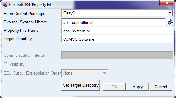
While in Adams Car, the files will be stored in the directory called 'external_system_libraries.tbl' in the default writable database, in the Adams View you select a target directory where the property file will be copied to. In both Adams Car and Adams View cases, the dynamic link library file will be copied into a sub directory named after the platform (win32, win64, linux32, linux64 and so on). This is to support a platform independent use of the property files. For instance, in the preceding example and on a win32 platform, the ESL property file and the ESL file will be copied into following locations:
C:/Temp/external_system_libraries/abs_system_version1.esl
C:/Temp/external_system_libraries/win32/abs_controller.dll
In case of HPUX platform, the full path to the copied library file would be:
C:/Temp/external_system_libraries/hpux/abs_controller.sl
Other platform follows the same principle.
Finally, if the control system type is set to ‘External System Library’, followings steps are internally performed by Adams (This is performed prior to an analysis - during reading property file procedure - in Adams Car and after a modify action of the system in Adams View):
1. Locates the ESL file referenced in the ESL property file. The path to the library file is
“path to ESL property file”/ “platform”/ “library file name”.(dll, so, sl ...)
2. Verifies that the dimension of the control system found in the ESL property file corresponds to the one defined in Adams Mechatronics, that is, matches the number of inputs and outputs
3. Activates the General State Equation (GSE) in the control system component and set the dimension of the different solver arrays related to the GSE
4. Reads the default parameter values and initial conditions defined in the ESL file.
5. Overrides the values of the parameters and initial conditions with the ones specified in the ESL property file
6. Copies the ESL file to the working directory (as Adams Solver expects the library file to be located in the working directory)
Activity settings
Imagine a scenario in Adams Car where you on the one hand have an assembly with both mechanical subsystems and control subsystems, and on the other hand have an assembly with only the mechanical subsystems. In such a scenario, you do not want to store different versions of the same mechanical (subsystem) template just because they refer to a control system which may or may not be part of the assembled model.
To allow using the same mechanical template regardless of whether it will be used in an assembly with control systems or without control systems, the concept of Activity Type is introduced for transducer/actuator signals. By using different Activity Types in conjunction with selected strategies for implementing the actuators influencing the mechanical behavior, you can make the mechanical templates compatible with both user scenarios.
When you create a transducer/actuator signal, you can select the signal activity type. In the table below, a summary of the different activity options and the corresponding consequences is shown.
When setting up your templates to be used both with and without control systems, there are two "levels" of activities. One level deals with setting up the activity of the transducer/actuator signal itself that is named Activity Type and determines whether the signal should be written into adm file or not. The other level is signal connectivity status which deals with whether the signal is connected to the control system, actuators, or components of the mechanical system. You can also define activity of a group of Adams objects to be dependent on the signals’ connectivity. Table below shows different alternatives for signal activity and signal connectivity. The table columns are explained thereafter.
Activity Type | Connected | Referred to | Signal Activity state | Active object state | |
|---|---|---|---|---|---|
Always | YES | ON | ON | ||
NO | ON | OFF | |||
Only if connected | YES | ON | ON | ||
NO | OFF | OFF | |||
Only if referred to | YES | YES | ON | ON | |
NO | OFF | OFF | |||
NO | YES | ON | OFF | ||
NO | OFF | OFF | |||
Activity Type:
Activity Type deals with setting up the activity of the transducer/actuator signal itself and the following types of activity are possible.
1. Always: as the name implies, the transducer signal or actuator signal would be always active in the model
2. Only if connected: the transducer or actuator signal only would be active when it has been connected to the appropriate control system input/output. In other words, it will not be visible in the .adm file if it has not been connected
3. Only if referred to: the actuator signal will be active only if another object in the model is referring to it. As an example, consider the use of a conventional mechanical damper object. You could replace that damper with a controlled one, and then automatically have the associated actuator signals become active, since they are referred to by that controlled damper object
Note that the later (“Only if referred to”) option is only applicable to actuator signal (i.e., not applicable to transducer signals).
Connected
This indicated whether the transducer/actuator signal has been connected or not to a control system input/output. In each transducer and actuator signal object there is a variable which keeps track of whether the transducer or actuator signal has been connected to the control system input/output. The name of this variable is signal_connectivity_flag; and its value is 1 if the connection is successful and 0 if there is no connection made. You can also use this variable in function expressions in the mechanical template to build in logic supporting the use of the template both with and without control systems.
Referred to
For each type of activity and connection status, the actuator signal may or may not be used in an expression of some other (mechanical) object, i.e. referred to. If it is referred to by another object, then the transducer/actuator signal object will be active in the model.
Signal Activity State
This indicates the activity of the transducer/actuator signal itself and determines whether the signal is written into adm file or not.
Active Object State
This indicates the activity state of those objects which have been selected (if any) to be in the "Active Objects" group when you created the transducer or actuator signal. This allows you to use the connectivity of the transducer/actuator signal as a trigger to set activity of arbitrary other objects in your subsystem. For example, you could have two actuators acting on a brake disk and have one dependent on the control signal passed through the actuator signal and the other dependent on the open-loop driver demand. You could thus let only one be active at the time, dependent on the connectivity of the actuator signal.
“Intelligent” modeling
When selecting the type of signal activity, you should have a strategy in mind in terms of how to use the transducer/actuator signal in the mechanical system. Let us consider a brake torque as an example. Normally, the brake torque actuator force expression would be a function of the brake_demand signal from the driver model. If you want to let the ABS system control the brake torque, you would instead make the brake torque actuator function be dependent on an actuator signal. However, if you want to be able to use the same brake subsystem in both assemblies with and without the control system subsystems, you have a couple of alternatives as follows to make the brake torque "intelligent" enough:
Alternative 1, use signal_connectivity_flag
In this case, the function expression for the brake torque actuator would look something like
FUNCTION = (1-signal_connectivity_flag) * F(brake_demand) + signal_connectivity_flag * F(actuator_signal)
In this alternative, suitable activity settings for the actuator signal object would be 'Always' or 'Only If Referred To'.
Note: | If you would use 'Only If Connected', you would get an error message in the Solver in case the actuator signal is not connected, i.e. if you try to use this brake system with no control subsystem in the assembly. This is because the signal_connectivity_flag will be deactivated and thus no longer visible in the .adm file, and thus the function expression refers to a non-existing object. |
Alternative 2, use Active/Inactive Objects
Instead of, as in the previous example, writing a complex function expression for one torque actuator object, you can create two torque actuators. Then you let one actuator be dependent on the brake_demand variable, and the other actuator be dependent on the actuator signal object. When you create the actuator_signal, you simply select the ‘arrow button’ to display a dialog box where you can put the proper actuator objects in the Active Object group and Deactive Object group. In this way, Adams Mechatronics will automatically switch the activity of the two torque actuators if the actuator signal is connected to (or disconnected from) the control system. In other words, you should in this case use the 'Always' or 'Only If Connected' activity setting when you create the actuator signal.
Note: | In this case, the only difference between the use of 'Always' and 'Only If Connected' will appear when the actuator signal is not connected. What happens with 'Always' then is that the actuator signal will stay active, producing only zero output whereas with 'Only If Connected', the actuator signal will be deactivated, thus not being visible to the Solver. |
Alternative 3, use UDE replace
If you are working with UDE components, there is a third alternative. For example, if you replace a conventional damper with an active damper, you want the actuator signal from the control system to automatically connect to the damper force object. An example of an active damper has been included in the Mechatronics installation as the amech damper. If your UDE is already created and implemented in Adams Mechatronics continue at step 2.
1. Create the UDE with the necessary elements and dependencies. The UDE is created as any other UDE with a few alterations described here. The actuator has to be created in the UDE as a data element variable
data_element create variable &
variable_name=.tmp_damper.actuator_signal &
function="0"
The actuator variable is then implemented in the UDE as intended, for example in a force expression
force modify direct single_component_force &
single_component_force_name=.tmp_damper.force &
function=".tmp_damper.scale_factor*VARVAL(.tmp_damper.actuator_signal)" &
i_marker_name=(.tmp_damper.i_marker) &
j_marker_name=(.tmp_damper.j_marker)
When the UDE is created the actuator variable has to be defined as an object
ude create definition &
def=.AMECH.udes.ac_amech_damper &
inp=.tmp_damper.i_marker, &
.tmp_damper.j_marker &
par=.tmp_damper.scale_factor, &
.tmp_damper.geoScale &
obj=.tmp_damper.force, &
.tmp_damper.actuator_signal, &
.tmp_damper.graphic, &
.tmp_damper.dmCalc, &
.tmp_damper.request
When the UDE is created in the correct approach, it is time to look at the methods used to handle the UDE. To be able to use UDE replace to turn on and off the control system the replace method has to include a command to find the actuator signal
macro create &
macro=.AMECH.udes.ac_amech_damper.replace &
user_entered_command="amech template_builder instance ac_amech_damper replace" &
wrap_in_undo=no &
commands="! $instance_name:t=ac_amech_damper", &
"!END_OF_PARAMETERS", &
"!", &
"amech toolkit get actuator_signal &", &
" entity=$instance_name &", &
" function_object=$instance_name.actuator_signal", &
"", &
"ude modify instance instance_name=$instance_name"
Now the UDE is created and the replace method handles the connection to the actuator signal. But to be able to replace another damper with the new active damper our new UDE has to be added to the same group
ude modify definition &
def=.AMECH.udes.ac_amech_damper &
isa=.ACAR.forces.ac_damper
The UDE is now created in the correct way and ready to be used in models.
There are a few utility macros available in Adams Mechatronics. These macros are designed to perform some simple tasks and can be used in developing new UDEs. Utility macros together with definition, macros and templates for the active damper can be found under examples in the installation.
The first macro can be used to find the related actuator signal, it returns a variable with the name of the actuator
amech toolkit find actuator_signal &
entity = (the entity for which you want to find a dependency) &
actuator_variable = (a variable where the macro will return the actuator signal)
The second macro finds the control system connected to a control signal
amech toolkit find control_system &
control_signal = (the control signal for which you want to find the control system) &
control_system_variable = (a variable where the macro will return the control system)
The last macro look at the type of your function object and adjust it to be dependent of the actuator signal. If your function object is a gforce or vforce you can specify in which direction the adjustment should be done
amech toolkit get actuator_signal &
entity = (the entity for which you want to create a dependency) &
function_object = (the object that should be dependent of an actuator signal)
2. The template is created with the standard element, in our example the standard damper. Even though the standard damper isn't connected to any actuator signals it is essential to plan ahead and create the actuator signal needed by the active damper. When you create the actuator signal you use the button to specify the UDE object that should be dependent on the actuator signal.
3. In the standard interface, when working with subsystems, the standard damper can be replaced by an active damper of our amech_damper type. Right-click on the damper for which you want to change UDE definition, and choose Replace. The definition for the new UDE appears in the list if it is implemented correctly. Our active damper is called Amech_damper.
Adams Mechatronics replaces the standard damper with a damper of the Amech_damper type and then finds the actuator associated with the damper. The dialog box for modifying the damper appears automatically (if you create your own UDE you have to create your own modify dialog box). In the dialog box you can see the name of the actuator signal, and if the actuator signal in turn is connected to a control system also the name of the control system is displayed in the dialog box. Use the modify buttons to the right to modify the actuator signal and the control system. The name of the control system will appear in this dialog box when you have connected the actuator signal to a control system in the signal manager.
4. You can switch between a standard damper and an active damper by using replace in both directions. The UDE definition that is in use when the subsystem is saved will be the default UDE definition in that subsystem.