Template Builder - Create ESP and ABS control Systems
Overview
This tutorial guides you through the process of creating the appropriate transducer signals, actuator signals and control systems in the Template Builder mode. One ABS control system and one ESP (Electronic Stability Program) control system will be created. Required transducer and actuator signals will be created in the body and brake system templates.
It is assumed that you have already started Adams Car and loaded the Adams Mechatronics plug-in.
The overall Template Builder process is:
1. Create control systems
2. Create transducer signals in appropriate templates
3. Create actuator signals
4. Invoke actuator signal variables in appropriate force/motion expressions in the mechanical system
Note that you can also create transducer signals and actuator signals before creating the control system, that is, using the following process:
1. Create transducer signals in appropriate templates
2. Create actuator signals
3. Invoke actuator signal variables in appropriate force/motion expressions in the mechanical system
4. Create control systems
The main steps in the tutorial are listed as:
■Create an ABS control system
■Create transducer signals in body and brake system template
■Create actuator signals in brake system template
■Create an ESP control system
■Create transducer signals in body template
Create an ABS control system
An ABS control system with following specification will be created:
Inputs:.
# | Name | Unit type | Unit string | Get transducer/control system output signal from: |
|---|---|---|---|---|
1 | brake_demand | user | no_units | brake_system |
2 | ESP_active | user | no_units | control_system (ESP) |
3 | body_long_vel | velocity | mm/sec | body |
4 | ESP_signal_front_left | user | no_units | control_system (ESP) |
5 | ESP_signal_front_right | user | no_units | control_system (ESP) |
6 | ESP_signal_rear_left | user | no_units | control_system (ESP) |
7 | ESP_signal_rear_right | user | no_units | control_system (ESP) |
8 | wheel_speed_front_left | angular_velocity | rad/sec | brake_system |
9 | wheel_speed_front_right | angular_velocity | rad/sec | brake_system |
10 | wheel_speed_rear_left | angular_velocity | rad/sec | brake_system |
11 | wheel_speed_rear_right | angular_velocity | rad/sec | brake_system |
Outputs:
# | Name | Unit type | Unit string | Transmit to actuator signal in: |
|---|---|---|---|---|
1 | ABS_signal_front_left | user | no_units | brake_system |
2 | ABS_signal_front_right | user | no_units | brake_system |
3 | ABS_signal_rear_left | user | no_units | brake_system |
4 | ABS_signal_rear_right | user | no_units | brake_system |
Note that five input transducers need to be created in the brake system template and one in the body template. This particular example of ABS system also uses input signals from another control system, that is, the ESP controller.
Units
Please note the usage of Unit Type and Unit String. Units are handled in Adams Mechatronics as follows:
You may specify units for transducer signal, actuator signal and control system input/output.
Unit Type indicates which kind of unit you are using, for example velocity or torque. Adams Mechatronics allows only connection of the same unit types when assigning a transducer to a control system input. The same principle applies when you
■assign a control system output channel to another control system's input channel
■assign a control system output channel to an actuator
The unit string is used by Adams Mechatronics to calculate the appropriate conversion factor. For example, if you define the wheel speed transducer to send out mm/s and your control system requires km/h, the conversion is automatically taken care of by Adams Car Mechatronics.
There is a set of pre-defined unit types and unit strings available in Adams Car Mechatronics. If your control system is working with other types of units, you can create your own units. See the following table for more information.
Unit type | Unit string | Used when signal from: | Comment |
|---|---|---|---|
user | no_units | desired unit type is not available in the pre-defined unit type list. Unit string can't be composed using Adams View convention (see Units in Adams Mechatronics for more info) | No units conversion will be done if you use no_units in "both ends", e.g. in both transducer and control system input. You can use scale_factor to enforce a units conversion effect. |
user | user defined | desired unit type is not available in select list unit string can be composed using the Adams View convention (see Units in Adams Mechatronics for more info) | Make sure the same unit types are used in “both ends”, e.g. in both transducer and control system input. |
length, angle, ... | model units | the transducer/actuator/control signal is (or should be) dependent on model units | No units conversion if model units is used in both ends |
length, angle, ... | mm, centimeter, deg, ... | you want the transducer/actuator/control signal to be independent of model units. Example: user subroutine without units handling or generated control code | Always conversion |
length, angle, ... | user defined | you need a unit which is not available in the pre-defined unit string list | Unit string can be composed using the Adams View convention (see Units in Adams Mechatronics for more info). Make sure to use the appropriate unit strings for the unit type selected. |
Creating the control system
In this example, we choose to create the control system in a separate template with the major_role control_system. (We could have chosen to create the control system in any template. There is no limitation in this regard.)
Display the Create Control System dialog box via the menu Mechatronics → Control System → New:
Click on the  button in the lower left side of the Create Control Signal dialog box, to display a new dialog box, Control Signal Editor, in which you can specify information for each input and output signal:
button in the lower left side of the Create Control Signal dialog box, to display a new dialog box, Control Signal Editor, in which you can specify information for each input and output signal:
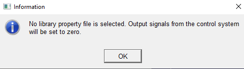
When you have entered all the information for the input and output signals, select Apply to save the information and return to the Create Control System dialog box. Select OK there. The following Message Window informs you that the control system output signals will be set to zero since no property file was selected.
Close the dialog box by selecting the OK button. The following Message Window appears to verify that the control system with given specification are created.
Close the message window and save the template. Proceed to create appropriate transducer signals.
Create transducer signals in body and brake system template
To feed the ABS controller with input signals from the vehicle model, we will add virtual transducer signals in the brake system and the body templates. The following transducer signals will be created:
Inputs to the control system were:
# | Name | Unit type | Unit string | Create transducer signal in: |
|---|---|---|---|---|
1 | brake_demand | user | no_units | brake_system |
2 | ESP_active | user | no_units | control_system (ESP) |
3 | body_long_vel | velocity | model_units | body |
4 | (left) ESP_signal_front | user | no_units | control_system (ESP) |
5 | (right) ESP_signal_front | user | no_units | control_system (ESP) |
6 | (left) ESP_signal_rear | user | no_units | control_system (ESP) |
7 | (right) ESP_signal_rear | user | no_units | control_system (ESP) |
8 | (left) wheel_speed_front | angular_velocity | rad/sec | brake_system |
9 | (right) wheel_speed_front | angular_velocity | rad/sec | brake_system |
10 | (left) wheel_speed_rear | angular_velocity | rad/sec | brake_system |
11 | (right) wheel_speed_rear | angular_velocity | rad/sec | brake_system |
Note that five input transducer signals need to be created in the brake system template and one in the body template. This particular example of ABS system also uses five input signals from another control system, that is, the ESP controller (control system output channels).
Units
Please note the use of Unit Type and Unit String and how the units differ from those defined in the control system. Adams Mechatronics will automatically convert the units from the transducer to the control system.
Creating the transducer signals
Open the template _brake_system_4Wdisk_mech_00.tpl from the <amech_shared> database:
Create the five transducer signals in the brake system. Use the following menu to display the dialog box for creating transducer signals:
We will start by creating the 'brake_demand' transducer signal. Use the Function Builder (click on the [...] button on the right) to enter the expression for the brake demand. After completing function expression in the Function Builder select Apply to go back to Create Transducer Signal dialog box and fill the Function text field. Note that you have the possibility to set request and measure activity on or off, and if you set it on, you can select which unit you want the signal to be expressed in.
We use the same method to create the wheel_speed_front transducer signals. Note that the Unit Type and Unit String are changed to angular_velocity and rad/s, respectively. Also note that we here take advantage of the left/right symmetry capability. Let's start by setting the expression for the front left wheel speed transducer signal:
Now we will set the expression for the right front transducer:
The reason why we ‘hardcode’ the unit string to rad/s is that the results from the solver variables left/righ_wheel_omega always are expressed in rad/s regardless of model units.
Click Apply to execute the dialog box. Note that you have now created two transducers, ue[l,r]_cst_wheel_speed_front.
Repeat this procedure for the rear wheel speed transducer signals (name them wheel_speed_rear).
Save the template and then open the _rigid_chassis_lt_mech_00.tpl template from the <amech_shared> database. We will now create the body longitudinal velocity transducer signal:
Note the use of a scale factor of -1 to switch sign of the signal before sending it into the ABS controller.
Save the body template. Proceed to create the actuator signals.
Creating the actuator signals in brake system template
We have now created all necessary transducer signals in the brake system and the body. Our next step is to create the actuator signals which control the brake torque in the brake system. Use View → Template to display the brake system template again.
The following actuator signals will be created:.
# | Name | Unit type | Unit string | Create actuator signal in: |
|---|---|---|---|---|
1 | (left) ABS_signal_front | user | no_units | brake_system |
2 | (right) ABS_signal_front | user | no_units | brake_system |
3 | (left) ABS_signal_rear | user | no_units | brake_system |
4 | (right) ABS_signal_rear | user | no_units | brake_system |
Display the Create Actuator Signal dialog box via the menu Mechatronics → Mechanical System → Actuator Signal → New:
Click Apply. You have now created the two left/right actuators ue[lr]_csa_ABS_signal_front. Repeat for the remaining actuator signals left/right ABS_signal_rear.
Connecting the actuator signals to the mechanical system
To transfer the actuator signals into the mechanical system, in this case the brake torque, we will modify the existing expression used for the brake pressure.
Now use the menu Build → System Elements → State Variable → Modify to display the following dialog box (click on the [...] button to display the Function Builder). Start by modifying the ._brake_system_4Wdisk_mech_00.left_front_brake_line_pressure variable:
Notes:
1. The use of Insert Object Name with the All Objects option to replace the selected item with the uel_csa_ABS_signal_front.signal_variable object in the expression in the top of the Function Builder. Click Apply in the Function Builder to load the new expression into the Modify State Variable dialog box, and then click Apply there too.
2. We created an expression where we use the signal_connection_flag of the actuator signal object to make this template fully compatible with use both with and without a control system. By using the formula
(1 - signal_connection_flag) * brake_demand + signal_connection_flag * actuator_signal
we thus make the brake pressure dependent on the brake_demand instead of the control system signal when the actuator has not been connected, which of course happens if we do not have the control system subsystem in our assembly.
Repeat this process for the remaining state variables:
._brake_system_4Wdisk_mech_00.left_rear_brake_line_pressure
._brake_system_4Wdisk_mech_00.right_front_brake_line_pressure
._brake_system_4Wdisk_mech_00.right_rear_brake_line_pressure
For your reference, the following figures show how ADAMS looks for the right rear brake line pressure:
Save the template.
Please proceed to the Standard User Mode to create the assembly and run an analysis, or proceed to create the ESP control system first.
Create an ESP control system
Now the ESP control system with following specification will be created:
Inputs:
# | Name | Unit type | Unit string | Create transducer signal in: |
|---|---|---|---|---|
1 | body_lat_acc | acceleration | mm/s2 | body |
2 | body_yaw_rate | angular_velocity | rad/sec | body |
Outputs::
# | Name | Unit type | Unit string | Create transducer signal in: |
|---|---|---|---|---|
1 | ESP_active | user | no_units | control_system (ABS) |
2 | ESP_signal_front_left | user | no_units | control_system (ABS) |
3 | ESP_signal_front_right | user | no_units | control_system (ABS) |
4 | ESP_signal_rear_left | user | no_units | control_system (ABS) |
5 | ESP_signal_rear_right | user | no_units | control_system (ABS) |
Note that the five output channels will be connected to input side of ABS control system we created earlier. This is just to illustrate the possibility to connect several control systems to each other. Therefore no additional actuator signals need to be created in the mechanical system.
Creating the control system
In this example, we choose to create the control system in a separate template with the major_role control_system. Note that we could have chosen to create the control system in any template instead. There is no limitation in this regard.
Display the Create Control System dialog box via the menu Mechatronics → Control System → New:
Click on the  button in the lower left side of the Create Control Signal dialog box, to display a new dialog box in which you can specify information for each input and output signal:
button in the lower left side of the Create Control Signal dialog box, to display a new dialog box in which you can specify information for each input and output signal: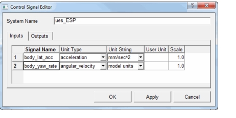
Close the message windows and save the template. Proceed to creating the transducers.
Creating the transducer signals
To feed the ESP controller with input signals from the vehicle model, we will add virtual transducer signals in the body template. The following transducer signals will be created:
Inputs to the ESP control system were::
# | Name | Unit type | Unit string | Create transducer signal in: |
|---|---|---|---|---|
1 | body_lat_acc | acceleration | model_units | body |
2 | body_yaw_rate | angular_velocity | rad/sec | body |
Units
Please note the use of Unit Type and Unit String and how the units differ from those defined in the control system. Adams Mechatronics will automatically convert the units from the transducer to the control system.
Creating the transducer signals
In the _rigid_chassis_lt_mech_00 template that you modified earlier, we will now create the body lateral acceleration transducer signal.
We will start by creating the 'body_lat_acc' transducer. Use Mechatronics → Mechanical System → Transducer Signal → New to display the following dialog box:
Create the yaw velocity transducer signal:
Save the body template and close it.
You have now successfully finished the Adams Car Mechatronics Template Builder tutorial.