Standard Interface - Setup and run co-simulation
Overview
This tutorial guides you through the process in the Standard Interface how to setup a control system for a co-simulation analysis. Steps on how to perform the co-simulation from the control package software are also included.
It is assumed that you have already started Adams Car and loaded the Adams Mechatronics plugin.
The main steps in the tutorial are listed below:
■Export plant
■Run co-simulation from control package software
Open assembly which includes ABS and ESP control systems
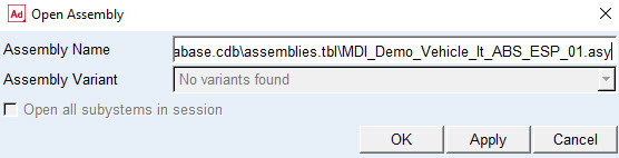
Open the demo assembly model MDI_Demo_Vehicle_lt_ABS_ESP_01.asy located in the Adams Mechatronics shared database:
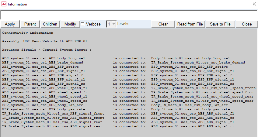
The assembly contains connectivity information about how to connect the different control system to each other and to the mechanical system. To verify the connectivity status of the control systems in the assembly by choosing Mechatronics → Info → Connectivity…
Modify ESP control system type
Both control systems in the assembly are of type ‘Function Expression’. However, in this tutorial we want to use the co-simulation functionality and we will therefore modify the ESP control system. To modify control systems use Mechatronics → Control System → Modify and fill in the dialog box:

The control package settings above will be the default choices in the export plant dialog box.
Run full vehicle analysis setup
Submit a single lane change manoeuvre to use it for a co-simulation:
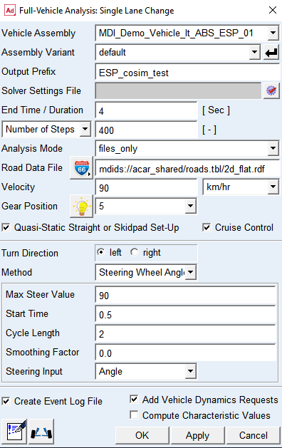
The mode of simulation choice ‘files_only’ is used create the Adams Car solver files needed for co-simulation. All files will be created in the working directory.
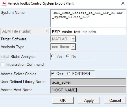
The following message will inform the user that one control system is of type ‘CoSim’ and Adams Mechatronics specific export plant dialog box will be displayed:
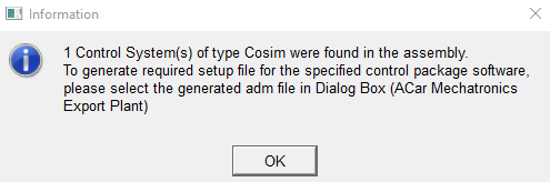
Press OK and select the previously generated file ESP_cosim_test_sin.adm in export plant dialog box. Keep default values of other the dialog box settings (also the Host Name):
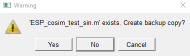
In the Warning message window, click Yes, if you want to create the backup copy or click No and proceed further.
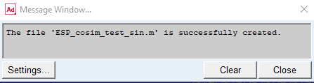
The Message Window will confirm the successful file creation.
Now everything is done in the Adams Car environment. All files that the control package needs for the co-simulation are created.
Run co-simulation from control package software
Start MATLAB and change working directory to the directory where the Adams Car files were created. At the MATLAB prompt type the name of the m-file, ESP_cosim_test_sin. All the signals are created.
Copy the following MATLAB and Simulink example files from install_dir/amech/examples/acar/simulink_models/esp_model to the working directory:
■esp_variables.m
■esp_cosim.mdl
The ESP model requires some variables to be set so remember to read them in from the esp_variables.m by typing esp_variables at the prompt.
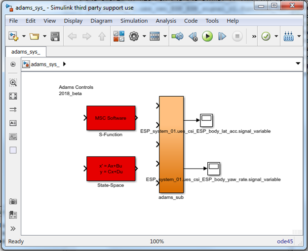
Create the Adams block by typing adams_sys at the prompt. This builds a new model in Simulink named adams_sys.mdl. This model contains the block representing the mechanical system:
Open the esp_cosim model and replace the adams_sub block with the adams_sub block you just created. This ensures that the proper version of the block will be used.
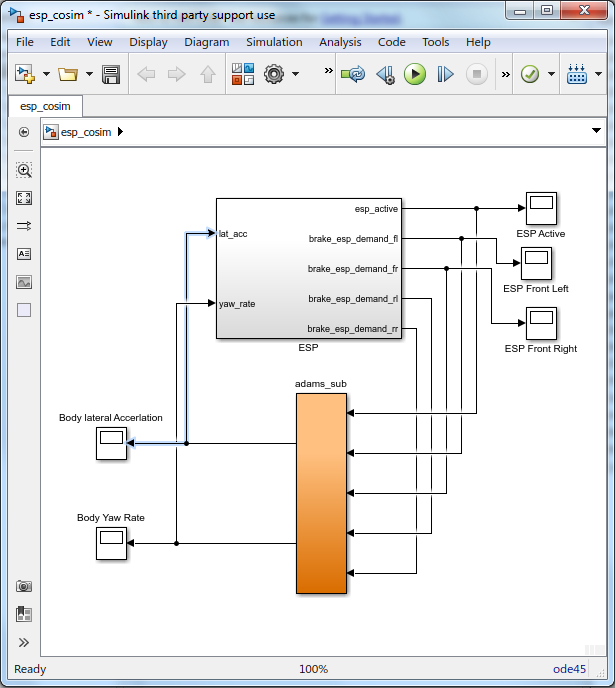
A tip is to flip the adams_sub block before replacing the old adams_sub_block (right mouse button click on adams_sub block → Format → Flip Block).
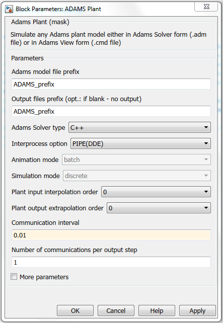
Set Communication Interval to 0.01 sec in the Adams Plant block (adams_sub block → Adams Plant). This time increment value corresponds to the output time step set in Adams Car analysis dialog box. Verify your block settings below:
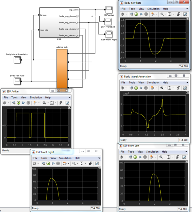
Start the MATLAB simulation. After the simulation the scope plots for the body yaw rate, body lateral acceleration, ESP active signal, ESP demand front left and right will look as below:
The Adams result file ESP_cosim_test_sin.res can also be read into Adams for plotting the results in Adams Postprocessor.
You have now finished the Adams Mechatronics Co-Simulation tutorial.