Gear Contact Pattern
Tools -> Gear Contact Pattern
For the option: | Do the following: |
|---|---|
Analysis | 'Last_Run' or analysis for which Contact pattern need to be plotted. It automatically populates 'maximum time' and 'minimum time' fields. |
Gear Force | Gear force for which contact pattern need to be plotted. The working directory contains the LPT file generated with same name as that of gear force. All results are derived from this LPT file. |
Minimum/Maximum Time | Time frame for which results need to be plotted. Selecting Analysis “RUN” select sets it to Start-End of simulation time. You can override this value. |
Tooth Selected | The Contact pattern is available only for the 'Gear_1', that is, first gear of the gear force definition as shown in below image. 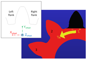 Tooth marked 'Black' is marked as first tooth. Numbering of gear teeth is marked by Arrow T1-Tn |
Flank | ■M(-) ■P(+) ■Both Based on sense of rotation: ■If Gear_1 (driver or Gear_1 in force definition) rotates counterclockwise then M(-) flank is in contact ■If Gear_1 (driver or Gear_1 in force definition) rotates clockwise then P(+) flank is in contact 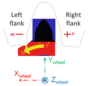 ■You can also opt to plot Both, if the gear_1 reverses direction of rotation while simulation and hence both flanks become driving at least once during simulation. The flank which is in contact with driven gear and hence drives the other gear is loaded and the pattern of loading can be plotted by this feature. |
Plot Options | |
Complete Time Frame | Plots of complete Simulation cycle. You can choose selected tooth for plot. |
All teeth | Plot of all teeth is generated instead of selected tooth. You can choose time-frame for which plot is needed. |
Select all (All teeth + complete time frame) | Plot of all teeth with complete time frame will be generated. |
Clear Existing Plots | Click to clear the existing plots. |
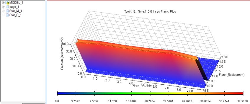
Example: Plot of Contact Pattern
Plot options
Flanks = Both : Note two plots in browser (Plot_M_1 and Plot_P_1)
Time Frame = Complete
Tooth Selected = 8
First Axis : Flank Radius (Starting from Contact_Start_Point to Contact_End_Point on tooth)
Second Axis: Gear Width
Third Axis: Pressure
Legend: Mentions tooth number, time frame and flank selected