FLEX_BODY
The FLEX_BODY statement defines a linear elastic body floating in space. The FLEX_BODY is capable of undergoing large motion, characterized by six non-linear generalized coordinates for a floating body coordinate system (BCS) relative to GROUND. The small, linear elastic deformations of the FLEX_BODY relative to this BCS are described by a linear combination of mode shapes. The modal amplitudes from this linear combination are additional generalized coordinates for the FLEX_BODY. The body can be connected to the rest of the mechanical system through applied forces and kinematic constraints.
Format
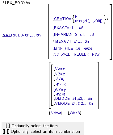
Arguments
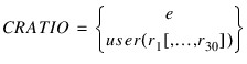 | Specify modal damping as a fraction of critical damping. You can specify modal damping using a function expression or a user-written subroutine. To define the modal damping with an expression, follow CRATIO with an equal sign and the expression. The FXFREQ and FXMODE function expression may be useful here. To define modal damping with a user-written subroutine, follow CRATIO with an equal sign, the character string USER, and the values (r1[,...,r30] that the Adams Solver (FORTRAN) is to pass to the DMPSUB user-written subroutine. If the CRATIO argument is used, it must either be the last argument in the FLEX_BODY statement, or be followed by a backslash (\). If you omit CRATIO, Adams Solver (FORTRAN) applies default damping as follows: ■1% to modes under 100 Hz ■10% to modes under 1 kHz ■Full critical damping to modes over 1 kHz You can disable the default damping by specifying CRATIO=0. |
DMODE=a1,a2,...,an | Specifies the initial values of the modal generalized coordinates. Default: 0 Range: Real values |
EXACT=c1:...:c6 | Specifies as many as six rigid body coordinates of the BCS that Adams Solver (FORTRAN) should not change as it iteratively solves for initial conditions which satisfy all constraints. The six coordinates are below. X - x coordinate Y - y coordinate Z - z coordinate PSI - Psi coordinate THETA - Theta coordinate PHI - Phi coordinate These coordinates can be entered in any order following EXACT. These are not changed by Adams Solver (FORTRAN) unless the values specified are inconsistent with initial conditions for a joint or motion. Default: None Range: X, Y, Z, Psi, Theta, or Phi |
INVARIANTS=c1:...:c9 | Specifies a true and false pattern indicating which of the nine inertia invariants Adams Solver (FORTRAN) should use to model inertia coupling of the flexible and rigid body motion. The order of the patterns corresponds to the nine successive inertia invariants. For more details on the inertia invariants, see the Theory of Flexible Bodies in Adams Flex. The following combinations have special significance: T:T:F:F:T:T:T:T:T - Full inertia coupling of deformation and rigid body motion. T:T:F:F:F:T:T:T:F - Ignore second-order deformation corrections to the inertia tensor, and the first-order corrections to the rotational and flexible inertia coupling. This is also called partial coupling. T:T:F:F:F:T:T:F:F - Neglect all deformation corrections to the mass matrix. *:*:*:*:*:F:*:*:* - Disable all deformations. The pattern T:T:F:F:F:T:T:T:F is the default, because although it potentially sacrifices small levels of accuracy compared to the first pattern of full inertia coupling, it does so with significant computational savings. If an MNF has six rigidbody modes in it, theoretically, invariants 3 and 4 should be zero even though there may be some non-zero entries in the MNF file due to numerical errors. This is the reason that they are disabled by default. The pattern T:T:F:F:F:T:T:F:F should be used with great care, because it only returns an accurate answer when the flexible component is quite rigid. The pattern *:*:*:*:*:F:*:*:*, where the * can be either T or F, offers a way to turn off all flexibility in the structure, usually for debugging purposes. Note that even with this last pattern, the FLEX_BODY statement does not function like a PART statement, due to formulation differences. It is hard to envision circumstances where it is appropriate to disable invariants 1 (the total mass), 2 (the undeformed CM location), and 7 (the undeformed inertia tensor). Disabling these normally causes a numerical singularity. Default: T:T:F:F:F:T:T:T:F |
MATRICES=id 1,...,idn | Specifies identifiers of matrices that contain the properties of the FLEX_BODY, such as inertia, node locations, mode shape information, applied modal loads, and preloads. Each matrix is defined via a MATRIX statement. Normally, these matrices are generated by a modal flexibility preprocessor (MNF2MTX) which writes these matrices to a file. To learn more about this process, see Translating an MNF or an MD DB into a Matrix File. The FLEX_BODY recognizes the following matrix names. Their identifiers can be specified in any order. SELMOD: A list of selected modes and their natural frequency. SELNOD: A list of selected nodes and their location. GENSTIFF: The generalized stiffness matrix. INVAR1: Invariant 1 - the total mass of the flexible body. INVAR2: Invariant 2 - the mass scaled center of mass location. INVAR3: Invariant 3. INVAR4: Invariant 4. INVAR5: Invariant 5. INVAR6: Invariant 6 - the generalized mass. INVAR7: Invariant 7 - the moment of inertia. INVAR8: Invariant 8. INVAR9: Invariant 9. T_MODE: Translational mode shape of selected modes at selected notes. R_MODE: Rotational mode shape of selected modes at selected nodes. PRELOAD: The preload on the selected modes. MODLOAD: The modal loadcases on the selected modes. Default: None Range: Adams identifiers |
MEXACT=d1, d2, ..., dn | Specifies as many as n modal body coordinates that Adams Solver (FORTRAN) should not change as it iteratively solves for initial conditions which satisfy all constraints. The variable n is the number of modes. The n coordinates are below. 1 to n Modal generalized coordinates Theses coordinates can be entered in any order following MEXACT. These are not changed by Adams Solver (FORTRAN) unless the values specified are inconsistent with initial conditions for a joint or motion. Default: None Range: Active mode numbers |
MNF_FILE=file_name | Specifies the path to the Modal Neutral File that defines the detailed properties of the flexible body. Note that this argument is not required by Adams Solver (FORTRAN) (see MATRICES argument above), only by Adams View. |
QG=x,y,z | Defines the Cartesian initial coordinates of the BCS with respect to the ground coordinate system. Default: 0.0, 0.0, 0.0 Range: Real values |
REULER=a,b,c | Defines the 3-1-3 Euler angles that Adams Solver (FORTRAN) uses to establish the initial orientation of the body coordinate system (BCS) with respect to the ground coordinate system. The a, b, and c rotations are in radians and are, respectively, about the z-axis of ground, new x-axis, and new z-axis of the BCS. To input Euler angles in degrees, you should add a D after each value. Default: 0.0, 0.0, 0.0 when REULER, XG, and ZG are omitted Range: Real values |
VM=id | Specifies the identifier of the marker that specifies the direction of translational velocity initial conditions (VX, VY, and VZ). VM defaults to global orientation. |
VMODE-a1,a2,...,an | Specifies the initial values of the time rate of change of the modal generalized coordinates. Default: 0 Range: Real Values |
VX=x,VY=y,VZ=z | Specifies the initial translational velocities of the body coordinate system (BCS) along the x-axis (VX), y-axis (VY), and z-axis (VZ) of the VM coordinate system. Default: 0 Range: Real values |
WM=id | Specifies the identifier of the marker that specifies the axes about which angular velocity initial conditions (WX, WY, and WZ) are defined. WM defaults to the BCS location and orientation. Furthermore, the origin of the WM marker lies on the axis of rotation. This is most useful for rotating systems. |
WX=a,WY=b,WZ=c | Specifies the initial rotational velocities of the body coordinate system (BCS) along the x-axis (WX), y-axis (WY), and z-axis (WZ) of the WM coordinate system. Default: 0 Range: Real values |
Tip: | ■All of the locations corresponding to a constraint attachment should have the finite element nodes associated with them. The nodal identifiers for these points are listed in the NODE argument. This allows for accessing the nodal information in the .adm file. ■The Modal Body Preprocessor provides the input matrices in the Adams Solver matrix format. See the online help for Adams Flex. ■When the nodal list is empty, the modal body cannot be attached to any other elements of Adams Solver (FORTRAN). ■The intrinsic variables FXMODE and FXFREQ are available so you can write function expressions that define CRATIO as a function of mode number and/or modal frequency (see FXMODE and FXFREQ functions). ■If your FLEX_BODY undergoes high-speed, rigid body rotations about a stationary axis, significant solver performance can be realized by aligning the z-axis of the body coordinate system (BCS) with the spin axis. Because the BCS of the FLEX_BODY is defined by the basic coordinate system in the finite element model, re-orientating the BCS with respect to the body requires you to re-orient the finite element model with respect to its basic coordinate system. In MSC.Nastran, this can be done easily with CORDxx Bulk Data entries. |
Caution: | ■When one of the following Joints or JPRIMS constrains a flexible body directly Adams Solver (FORTRAN) creates a dummy part and a dummy fixed joint connecting the dummy part to the flexible body at the location of the constraint, and then moves the constraint to the dummy part. Joints: ■CONVEL ■CYLINDRICAL ■PLANAR ■RACKPIN ■SCREW ■TRANSLATIONAL ■GEAR ■COUPLER JPRIMS: ■INLINE ■INPLANE ■When one of the following forces is applied directly to a flexible body Adams Solver (FORTRAN) creates a dummy part and a dummy fixed joint connecting the dummy part to the flexible body at the location of the force, and moves the force to the dummy part. ■BEAM ■BUSHING ■FIELD ■ROTATIONAL SFORCE ■ROTATIONAL SPRINGDAMPER ■Flexible body CONTACT is only supported when using Adams Solver (C++). |
Examples
FLEX_BODY/1
, MATRICES=1,2,3,4,5,6,7,8,9,10,11,12,13,14
, CRATIO=0.0\
, DMODE=.0,.0,.0,.0
, VMODE=.0,.1,.0,.0
, MATRICES=1,2,3,4,5,6,7,8,9,10,11,12,13,14
, CRATIO=0.0\
, DMODE=.0,.0,.0,.0
, VMODE=.0,.1,.0,.0
This statement defines a flexible body with a damping ratio of 0.0 on all modes. Zero initial modal displacements are specified by the DMODE argument. The VMODE argument specifies an initial modal velocity for mode 2 of 0.1.
FLEX_BODY/1
, CRATIO = STEP(TIME, 0.1, 1.0, 1.2, STEP(FXFREQ, 3000, 0.02, 10000, 0.2))\
, CRATIO = STEP(TIME, 0.1, 1.0, 1.2, STEP(FXFREQ, 3000, 0.02, 10000, 0.2))\
This example specifies modal damping that varies both with time and modal frequency, such that all modes have 100% critical damping until t=0.1, after which:
■Modal damping decreases smoothly to between 2% and 20% of modal damping at time=1.2.
■Modes with modal frequencies less than 3,000 reach 2% modal damping.
■Modes with modal frequencies above 10,000 reach 20% modal damping.
■Modes with modal frequencies between 3,000 and 10,000 reach modal damping values smoothly distributed between 2% and 20%.
FLEX_BODY/1,
, CRATIO = IF(FXFREQ-100:0.01,0.1,if(FXFREQ-1000:0.1,1.0,1.0)\
, CRATIO = IF(FXFREQ-100:0.01,0.1,if(FXFREQ-1000:0.1,1.0,1.0)\
This example recreates the default modal damping scheme using nested IF function expressions.
See other Inertia and material data available.