GRAPHICS
The GRAPHICS statement creates:
■Two- or three-dimensional geometry for CONTACT. You always define the geometry with respect to a reference marker.
■Three-dimensional graphic data that represents the parts, constraints, or forces in a system.
Note: | The only graphic that can be defined on a flex body is a point. |
Because there are two uses for geometry, one for contact and the second for the graphical display of objects, we have divided the documentation into two separate sections:
New types of graphics are available for representing a wide variety of geometries in contact. Adams Solver does not write these new geometric entities (point, plane, ellipsoid, and external) to the graphics file, and therefore, they cannot be displayed in standalone Adams Solver (FORTRAN). You can, however, view them from Adams View.
Graphics for Contact
Format
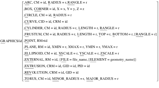
Arguments
ARC | Creates an arc. You use the following arguments to define the arc: ■CM to specify the center marker of the arc. ■RADIUS to define the radius of the arc. ■RANGLE to define the extent of the arc, with the arc always starting at the x-axis of the CM marker. ■SEG to specify the number of line segments to use to display the arc. |
BOTTOM=r | Defines the bottom radius of a frustum. |
BOX | Creates a rectangular box. You use the following arguments to define the box: ■CORNER to specify the ID of a reference marker at one corner of the box. ■X, Y, and Z to define the extent of the box along the x-, y-, and z-axes of the corner marker. |
CID=id | Specifies the identifier of the curve to be drawn. |
CIRCLE | Creates a circle. You use the following arguments to define the circle: ■CM to specify the center marker of the circle. ■RADIUS to specify the radius of the circle. |
CM=id | Defines the identifier of the marker at the center of an arc, circle, cylinder, frustum or torus. ■For an arc, circle, or ellipsoid, the origin of the marker specifies the center. ■For a cylinder or frustum, the origin of the marker specifies the center of the bottom circle. The bottom circle lies in the plane contained by the x- and y-axes of the marker. The z-axis of the marker defines the centerline axis of the cylinder or frustum. ■For a torus, the origin of the marker specifies the center of the torus. The z-axis of the marker defines the axis of revolution. |
CRM=id | Defines the reference marker with respect to which the curve data points are specified. |
CORNER=id | Defines a reference marker, which is at a corner of the box that is being created. |
CURVE | Creates a curve graphic based on a CURVE statement. You define the curve data with respect to a reference marker (CRM). The CONTACTand CVCV modeling entities require that the curve be planar. It must be in the plane defined by the x- and y-axes of the RM marker, and must contain the origin of the marker. |
CYLINDER | Creates a cylinder whose top and bottom are perpendicular to the cylinder central axis. You use the following arguments to define the cylinder: ■CM to specify the center marker (CM) of the cylinder. The z-axis of the CM marker defines the axis of the cylinder. ■RADIUS to define the radius of the cylinder. ■RANGLE to define the angular extent of the cylinder, with the arc always starting at the x-axis of the CM marker. ■LENGTH to define the height of the cylinder. |
ELEMENT = geometry_name | Used with external geometry. Specifies the name of a geometric entity in a file that FILE identifies. The file can contain multiple geometries. You use ELEMENT to select a particular geometry from the file even when it contains just one geometry. You will need additional GRAPHICS statements if you want to read multiple geometries from the same file. |
ELLIPSOID | Creates an ellipsoid. You use the following arguments to define the ellipsoid: ■CM to specify the center marker (CM) of the ellipsoid. ■XSCALE, YSCALE, and ZSCALE to specify the diameters along the x-, y-, and z-axes of the CM marker. If the argument values are all equal (XSCALE = YSCALE = ZSCALE), then Adams Solver (FORTRAN) creates a sphere. |
EXTERNAL | Specifies that a three-dimensional solid geometry is to be created. The data for the geometries is in an external file that the geometry engine of Adams Solver (FORTRAN) can read. It use the following arguments to define the geometry: ■RM to specify the marker that defines the reference coordinate system. ■FILE identifies the file to be read. This file is commonly generated by the geometry engine being used. ■ELEMENT to specify the name of a geometric entity in a file that FILE identifies. Adams Solver (FORTRAN) uses the geometry package Parasolid 14.0 to understand geometry. Parasolid input files have the extension .xmt_txt and .xmt_bin. Both are supported, however, .xmt_bin files are not portable across platforms. Parasolid can read in the geometry data and tell Adams Solver (FORTRAN): ■Whether or not two geometries are in contact. ■Where the contact points are located on each geometry. ■The outward normals at the calculated contact points. |
EXTRUSION | Creates an extrusion graphic. You use following arguments to specify an extrusion: ■CRM to specify the id of the reference marker for the extrusion. ■GID to specify the id of the closed curve or circle graphic to be extruded. ■PID to specify the id of the curve, arc, or circle graphic to extrude along. |
FILE=file_name | Specifies the name of a file containing one or more geometric entities. Adams Solver (FORTRAN) can only read Parasolid files. Parasolids is an exact boundary representation (b-rep) geometric modeler. This means that it represents solids (and other types of geometry) by their boundaries. Other file formats (such as shell files) must be converted to a boundary representation externally before the Adams Solver (FORTRAN) Parasolid geometry engine can use them. |
FRUSTUM | Creates a frustum of a cone whose top and bottom are perpendicular to the cone central axis. You use the following arguments to define the frustum: ■CM to specify the center marker (CM) of the frustum. The z-axis of the CM marker defines the axis of the frustum. ■TOP and BOTTOM to define its top and bottom radii, respectively. ■RANGLE to define the angular extent of the frustum, with the arc always starting at the x-axis of the CM marker. ■RADIUS to define the radius of the frustum cone. ■LENGTH to specify the height of the frustum. |
GID=id | Defines the id of the closed curve or circle graphic to be revolved or extruded. |
LENGTH=r | Defines the height for either a cylinder or frustum. The two circles at the ends of a cylinder or frustum are both perpendicular to the z-axis of the CM marker. Therefore, the circles are parallel. Adams Solver (FORTRAN) uses the value of LENGTH to specify the z distance between the two circles. There is no limit on the value of r. A positive value specifies a cylinder or frustum along the positive z-axis of the CM marker, and a negative value specifies a cylinder or frustum along the negative z-axis of the CM marker. |
MAJOR_RADIUS | Specifies the larger radius of the torus. |
MINOR_RADIUS | Specifies the smaller radius of the torus. |
PID | Defines the id of the curve, arc, or circle graphic to extrude along. |
PLANE | Creates a finite plane. You use the following arguments to create a plane: ■RM to specify a reference coordinate system for the plane. The plane lies in the x-y plane of the RM marker (that is, the z-axis of the RM marker is normal to the plane). ■XMIN, XMAX, YMIN, and YMAX to specify the extent of the plane. The plane is a two-dimensional element, and, therefore, you can only use it when defining contact with another two-dimensional element (point, arc, circle, curve). |
POINT | Creates a graphic point at the origin of the RM marker. |
RADIUS=r | Defines the radius of a circle, arc, cylinder, or frustrum. Range: Radius > 0 |
RANGLE=r | Defines an angle measured positive (according to the right-hand rule) about the z-axis of the CM marker. Adams Solver (FORTRAN) assumes RANGLE is in radians. The angle starts at the positive x-axis of the CM marker and subtends the arc, the arc of the cylinder, or the arc of the cone frustum. Range: -2  < RANGLE < 2 < RANGLE < 2 |
REVOLUTION | Creates a revolution graphic. You use following arguments to define a revolution: ■CRM to specify the id of the marker that defines the center of revolution. The z-axis of the CMR marker is the axis of revolution. ■GID to specify the id of the closed curve or circle graphic to be revolved. |
RM=id | Identifies the marker that defines the reference coordinate system for a point, plane, or external geometric entity. Adams Solver (FORTRAN) defines the geometries in this coordinate system. |
TOP=r | Defines the radius at the top of a frustum. The top is perpendicular to the CM marker z-axis, and the center of the top is at the position on the CM marker z-axis that LENGTH specifies. There is no limit on the value of r. |
TORUS | Creates a torus graphic. You use the following arguments to create a torus: ■CM to specify the id of the marker that defines the center of the torus. The z-axis of the CM marker is the axis of revolution. ■MINOR_RADIUS to specify the smaller radius of the torus. ■MAJOR_RADIUS to specify the larger radius of the torus. |
X=x, Y=y, Z=z | Locates the vertex of the box that is diagonally opposite from the corner that the argument CORNER defines. You must specify the values of X, Y, and Z with respect to the marker coordinate system. |
XMIN=r, XMAX = y, YMIN = r, YMAX = r | Specifies the boundary edges of a plane. XMIN, XMAX, YMIN, and YMAX are relative to the CM marker of the plane. Range: XMIN < XMAX YMIN < YMAX |
XCALE = r, YSCALE = r, ZSCALE = r | Specifies the diameters along the x-, y-, and z-axes of an ellipsoid. Range: XSCALE > 0 YSCALE > 0 ZSCALE > 0 |
Examples for Content
GRAPHICS/0202, CYLINDER, CM=0201, RADIUS=2
, LENGTH=-2
, LENGTH=-2
This GRAPHICS statement creates a cylinder with its base at Marker 0201. Marker 0201 is located at the center of the circular cross-section, which has a radius of two. The cylinder has a length of two along the negative z-axis of Marker 0201.
GRAPHICS/1297, EXTERNAL, RM=7921,
, FILE = GenevaWheel.xmt_txt
, ELEMENT = Geneva
, FILE = GenevaWheel.xmt_txt
, ELEMENT = Geneva
This GRAPHICS statement creates a three-dimensional solid element. The data for this solid element is contained in a Parasolid file, GenevaWheel.xmt_txt. Within this file, which contains several geometric entities, the solid with a tag, Geneva, is to be extracted. The solid definition is specified with respect to Marker 7921.
The geometry associated with GenevaWheel.xmt_txt is shown next.
Geometry in Parasolid File GenevaWheel.xmt_txt
Graphics for Graphic Display of Objects
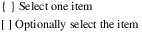
Format
Arguments
ARC | Creates an arc. |
BOTTOM=r | Defines the bottom radius of a frustum of a cone. The bottom is perpendicular to the center marker z-axis, and the center of the bottom is at the center marker origin. There is no limit on the value of r. |
BOX | Creates a box with parallel edges and orthogonal vertices. |
CID=id | Specifies the identifier of the CURVE statement to be drawn. Adams Solver (FORTRAN) generates a curve graphic in each marker reference frame you specify with CRM. |
CIRCLE | Creates a circle. |
CM=id | Defines the identifier of the marker at the center of an arc, circle, cylinder, frustum, or torus. If you are creating a circle or arc, orient the CM marker so that its z-axis is normal to the plane of the circle or plane of the arc. Similarly, if you are defining a cylinder or frustum, orient the CM marker so that its z-axis is normal to the bottom plane of the cylinder or the frustum. For the torus the z-axis should be the axis of the revolution. |
COILS | Defines the number of coils in the spring of a spring-damper (SPDP) graphic. Default: 0 Range: 99,999 > COILS > 0 |
CORNER=id | Defines a reference marker at a corner of the box to be created. |
CRM=id 1[,...,idn] | Specifies a list of up to 2,500 markers at which to draw the curve identified by CID. Adams Solver generates a curve graphic in each marker reference frame specified. |
CURVE | Creates a curve graphic based on a CURVE statement. |
CYLINDER | Creates a cylinder whose top and bottom are perpendicular to the cylinder central axis. |
DA=r | Defines the diameter of the spring in a spring-damper (see the spring-damper figure below). There is no limit on the value of r. Default: 0 |
DB=r | Defines the diameter of the damper in a spring-damper at the I marker (see the spring-damper figure below). There is no limit on the value of r. Default: 0 |
DC=r | Defines the diameter of the damper in a spring-damper at the J marker (see the spring-damper figure below). There is no limit on the value of r. Default: 0 |
Spring-Damper  | |
EID=id | Specifies the identifier of the element whose force is to be displayed by the FORCE graphic. You can not specify EID if ETYPE=ALL. |
EMARKER=id | Specifies the identifier of the marker where Adams Solver displays the force graphic. If ETYPE=ALL, marker EMARKER must have at least one force applied to it. If you enter a specific force type, and identifier EID, marker EMARKER must be one of the markers upon which the specified force acts. |
ETYPE = {ALL, BEAM, BUSHING, FIELD, SFORCE, SPDP, VFORCE, VTORQUE, GFORCE, NFORCE, JOINT, JPRIM, PTCV, CVCV} | Specifies the element type for which Adams Solver generates force graphics. In combination with EID, ETYPE specifies one force statement. If ETYPE=ALL, then Adams Solver sums all forces applied to the EMARKER. |
EXTRUSION | Creates an extrusion graphic. You use following arguments to specify an extrusion: ■CRM to specify the id of the reference marker for the extrusion. ■GID to specify the id of the closed curve or circle graphic to be extruded. ■PID to specify the id of the curve, arc, or circle graphic to extrude along. |
FORCE | Creates an arrow whose direction is identical to the direction of a force and whose length is proportional to the magnitude of a force. |
FRUSTUM | Creates a frustum of a cone whose top and bottom are perpendicular to the cone central axis. |
GID | Specifies the id of the closed curve or circle graphic to extruded or revolved. |
I=id, J=id | Defines the I and J markers for creating a spring-damper graphic. The I and J markers define the attachment points of the spring-damper. |
LA=r | Defines the distance between the I marker and the end of the damper to which it is closest (see the spring-damper figure ). There is no limit on the value of r. Default: 0 |
LB=r | Defines the distance between the J marker and the end of the damper to which it is closest (see the spring-damper figure). There is no limit on the value of r. Default: 0 |
LC=r | Defines the height of the damper at I. Adams Solver measures the height from the bottom of the damper to its top along the line segment between the I and J marker. There is no limit on the value of r. Default: 0 |
LD=r | Defines the height of the damper at J. Adams Solver measures the height from the bottom of the damper to its top along the line segment between the I and J marker. There is no limit on the value of r. Default: 0 |
LENGTH=r | Defines the height for either a cylinder or frustum. Because the two circles at the ends of a cylinder or frustum are both perpendicular to the z-axis of the CM marker, they are parallel. Adams Solver (FORTRAN) uses the value of LENGTH to specify the z distance between the two circles. There is no limit on the value of r. A positive value specifies a cylinder or frustum along the positive z-axis of the CM marker, and a negative value specifies a cylinder or frustum along the negative z-axis of the CM marker. |
MAJOR_RADIUS | Defines the larger radius of the torus. |
MINOR_RADIUS | Defines the smaller radius of the torus. |
OUTLINE=id1[,...,id2500] | Creates visible and invisible line segments to connect at least two and not more than 2,500 markers. The values id 1[,...,id 2500] are marker identifiers. They define an outline of line segments that Adams Solver (FORTRAN) draws from one marker to the next. A comma (,) between two marker identifiers causes Adams Solver (FORTRAN) to draw a line segment between two markers. A comma and minus sign (,-) between two marker identifiers causes Adams Solver (FORTRAN) to draw an invisible line from the first marker to the second. |
PID | Specifies the id of the curve, arc, or circle graphic to extrude along. |
RADIUS=r | Defines the radius of a circle, arc, or cylinder. There is no limit on the value of r. |
RANGLE=r | Defines an angle measured positive (according to the right-hand rule) about the z-axis of the CM. Adams Solver (FORTRAN) assumes RANGLE is in radians. The angle starts at the positive x-axis of the CM marker and subtends the arc, the arc of the cylinder, or the arc of the cone frustum. Adams Solver (FORTRAN) clips to -2  values of r less than -2 values of r less than -2 and clips to 2 and clips to 2 values of r greater than 2 values of r greater than 2 . .Range: 2  > r > -2 > r > -2 |
REVOLUTION | Creates a revolution graphic. You use following arguments to define a revolution: ■CRM to specify the id of the marker that defines the center of revolution. The z-axis of the CMR marker is the axis of revolution. ■GID to specify the id of the closed curve or circle graphic to be revolved. |
RM=id | Defines the radius of a circle, arc, or cylinder. Adams Solver (FORTRAN) measures the distance from the CM marker to the RM marker to determine the radius. |
SEG=i | Defines the number of straight line segments Adams Solver uses to draw a curve, circle, an arc, or the two circles at the ends of a cylinder or a frustum. Default: 20 Range: 99,999 > SEG > 0 |
SIDES=i | Defines the number of straight line segments Adams Solver draws between the two parallel circles of a cylinder or a frustum. Default: 20 Range: 99,999 > SIDES > 0 |
SPDP | Draws a spring-damper graphic representation (see the spring-damper figure). For SPDP, use I and J. To draw just the spring, use DA and COILS. To draw just the damper at the I marker, use DB, LA, and LC. To draw just the damper at the J marker, use DC, LB, and LD. To draw the entire spring-damper, use all of the arguments for SPDP. DA, DB, DC, LA, LB, LC, LD, and COILS are all optional, but Adams Solver cannot draw anything unless you include (at a minimum) the arguments for the spring or one of the dampers. |
TOP=r | Defines the radius at the top of a frustum. The top is perpendicular to the CM marker z-axis, and the center of the top is at the position on the CM marker z-axis that LENGTH specifies. There is no limit on the value of r. |
TORUS | Creates a torus graphic. You use the following arguments to create a torus: ■CM to specify the id of the marker that defines the center of the torus. The z-axis of the CM marker is the axis of revolution. ■MINOR_RADIUS to specify the smaller radius of the torus. ■MAJOR_RADIUS to specify the larger radius of the torus. |
X=x,Y=y,Z=z | Locates the vertex of the box that is diagonally opposite from the corner defined by CORNER. The values of X, Y, and Z must be specified with respect to the marker coordinate system. |
Extended Definition
The GRAPHICS statement creates three-dimensional graphic data for display on a graphics device. You can use it to create line segments, boxes, curves, circles, arcs, cylinders, frustums of cones, and spring-dampers. Combinations of these images are attached to parts (including ground) to approximate their appearance. These images move with their respective parts to produce a graphic simulation of the mechanism behavior. You can also use the GRAPHICS statement to create force vectors so that the forces in the system can be displayed.
Examples for Graphic Display of Objects
GRAPHICS/0202, CYLINDER, CM=0201, RADIUS=2
, LENGTH=-2, SIDES=20, SEG=20
, LENGTH=-2, SIDES=20, SEG=20
This GRAPHICS statement creates a cylinder with its base at Marker 0201. Marker 0201 is located at the center of the circular cross-section, which has a radius of two. The cylinder has a length of two along the negative z-axis of Marker 0201. Twenty sides define the body of the cylinder, and the circles at the top and at the bottom of the cylinder are actually twenty-sided polygons.
GRAPHICS/0001, OUTLINE=1001,1002,-1003,1004
This GRAPHICS statement creates a line from Marker 1001 to Marker 1002 and creates a line from Marker 1003 to Marker 1004. Because a minus sign (-) precedes Marker 1003, the statement creates an invisible line segment from Marker 1002 to Marker 1003.
See other bordered available.