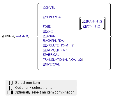
JOINT
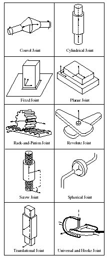
The JOINT statement describes a physically recognizable combination of constraints that are used to connect bodies (rigid and flexible) together. Examples of joints include constant-velocity, cylindrical, fixed, Hooke, planar, rack-and-pinion, revolute, screw, spherical, translational, and universal joints.
Format
Arguments
CONVEL | Indicates the joint is a two-degree-of-freedom joint that allows rotation about two axes: the zi and zj axes (see the figure below). For the CONVEL joint, Adams Solver (FORTRAN) superimposes the origins of the I and J markers and constrains the rotation about the z-axis of the I marker to be equal and opposite to the rotation about the z-axis of the J marker. When connecting two shafts, the z-axes of the I and J markers should point down the shafts, away from the center of the joint. Additionally, the angle between the x-axis of the I marker and the y-axis of the J marker must be the same as the angle between the y-axis of the I marker and the x-axis of the J marker. The easiest way to ensure the x and y axes are properly aligned is to make the I and J x-axes parallel, or the I and J y-axes parallel. |
Convel Joint 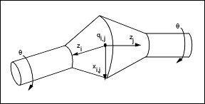 | |
CYLINDRICAL | Indicates that the joint is a two-degree-of-freedom joint that allows both relative translational and relative rotational displacement of one part with respect to another (see the figure below). I marker translation along the zj axis and rotation about the zj axis are permitted. For the CYLINDRICAL joint, Adams Solver (FORTRAN) keeps the z-axis of the I marker parallel to, and co-directed with, the z-axis of the J marker and confines the origin of the I marker to the z-axis of the J marker so that the I and J markers have a common z-axis. To determine translational motion, Adams Solver (FORTRAN) measures the movement of the origin of the I marker along the z-axis and with respect to the J marker. To determine rotational motion, Adams Solver (FORTRAN) measures the rotation of the x-axis of the I marker about the common z-axis and with respect to the x-axis of the J marker. |
Cylindrical Joint 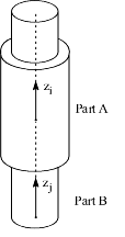 | |
FIXED | Indicates the joint is a zero-degree-of-freedom joint that completely locks the I and J markers together (see the figure below). For the FIXED joint, Adams Solver (FORTRAN) superimposes the origins and the axes of the I and J markers, allowing no relative motion. |
Fixed Joint 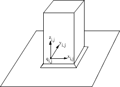 | |
HOOKE | Indicates the joint is a two-degree-of-freedom joint that allows rotation about two axes: xi, the x-axis of the I marker and yj, the y-axis of the J marker (see the figure below). For the HOOKE joint, Adams Solver (FORTRAN) superimposes the origins of the I and J markers and constraint markers. It also keeps the x-axis of the I marker perpendicular to the y-axis of the J marker so they outline the crosspiece of the joint. The origins of the I and J markers are at the center of the cross. The HOOKE joint functions the same as the universal joint, but uses different marker orientations. |
Hooke Joint 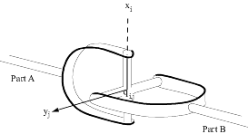 | |
I=id, J=id | Specifies the identifier of one fixed marker in each part the joint connects. Adams Solver (FORTRAN) connects one part at the I marker to the other at the J marker. |
IC=r1,r2 | Defines the initial conditions you want to impose on either a translational or revolute joint. The value r1 is the velocity of the I marker with respect to the J marker as seen by the J marker. The value r2 is the displacement of the I marker with respect to the J marker. Adams Solver (FORTRAN) measures both the rotational velocity and the rotation of the x-axis of the I marker about the common z-axis of the I and J markers with respect to the x-axis of the J marker. The IC argument imposes a constraint that is active only during initial conditions analysis (not at the time of the initial configuration). Adams Solver (FORTRAN) does not impose initial conditions during subsequent analyses. If the IC argument imposes initial conditions on the joint that are inconsistent with those on one of the bodies the joint connects, the initial conditions on the joint have precedence over those on the body. For the initial conditions for a translational joint, velocity is in units of translational displacement per unit of time and displacement is in units of length. For the initial conditions for a revolute joint, velocity is in radians per unit of time and displacement is in radians. |
ICROT=r1,r2 | Defines the rotational initial conditions you want to impose on a cylindrical joint. The value r1 is the angular velocity of the I marker with respect to the J marker (in radians per unit of time). The value r2 is the rotation of the I marker with respect to the J marker (in radians). Adams Solver (FORTRAN) measures both the rotational velocity and the rotation of the x-axis of the I marker about the common z-axis of the I and the J markers with respect to the x-axis of the J marker. The ICROT argument imposes a constraint that is active only during initial conditions analysis (not at the time of the initial configuration). Adams Solver (FORTRAN) does not impose initial conditions during subsequent analyses. If the ICROT argument imposes initial conditions on the joint that are inconsistent with those specified on one of the bodies the joint connects, the initial conditions on the joint have precedence over those on the body. |
ICTRAN=r1,r2 | Defines the translational initial conditions you want to impose on a cylindrical joint. The value r1 is the translational velocity of the I marker with respect to the J marker (in units of length per unit of time). The value r2 is the translation of the I marker with respect to the J marker (in units of length). Adams Solver (FORTRAN) measures both translational velocity and translation at the origin of the I marker along the common z-axis of I and J and with respect to the J marker. The ICTRAN argument imposes a constraint that is active only during initial conditions analysis (not at the time of the initial configuration). Adams Solver (FORTRAN) does not impose initial conditions during subsequent analyses. If the ICTRAN argument imposes initial conditions on the joint that are inconsistent with those specified on one of the bodies the joint connects, the initial conditions on the joint have precedence over those on the body. |
PD=r | Pitch diameter (PD) defines the pitch diameter of the pinion gear of a rack-and-pinion joint. The pitch diameter relates the rotational motion of the pinion to the translational motion of the rack. When the pinion turns in the positive direction around the z-axis of the I marker, a positive pitch diameter moves the rack in the positive direction along the z-axis of the J marker and a negative pitch diameter moves the rack in the negative direction along the z-axis of the J marker. |
PITCH=r | Defines the translational displacement of a screw joint that corresponds to one revolution of its rotational displacement. A positive pitch creates a right-hand thread, and a negative pitch creates a left-hand thread. |
PLANAR | Indicates that the joint is a three-degree-of-freedom joint that allows a plane of one part to slide on a plane on a second part (see the figure below). The x and y axis of the I and J markers of the joint define the planes on the two parts. For the PLANAR joint, Adams Solver (FORTRAN) constrains the z-axis of the I marker so that it remains parallel to, and co-directed with, the z-axis of the J marker and does not allow the linear displacement with respect to the J marker to have a z component. |
Planar Joint 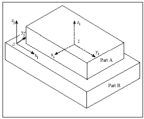 | |
RACKPIN | Indicates that the joint is a five-degree-of-freedom joint that constrains the rotational displacement of the I marker to the translational displacement of the J marker and measures both displacements with respect to the J marker. The I marker is at the center of the pinion, and the J marker is in the rack. The figure below illustrates a rack-and-pinion joint. For the RACKPIN joint, the z-axis of the pinion must be parallel to and co-directed with the x-axis of the rack. The separation between the two axes should be one-half the pitch diameter of the pinion. The rack-and-pinion joint itself does not enforce the position and orientation it requires, but the chain of both parts and joints that connects markers I and J should enforce the position and orientation. A common approach for enforcing the position and orientation is to support the rack with a translational joint and to support the pinion with a revolute joint. During simulation, the I marker displacement parallel to the J marker z-axis is a function of the angle between the I marker x-axis and the J marker z-axis. Adams Solver (FORTRAN) measures a positive rotation according to the right-hand rule. For every full rotation, the distance the I marker moves parallel to the z-axis of the J marker is equal to the value of PD times p. The direction the I marker moves depends on the sign of PD. For a positive PD and positive rotation, the I marker moves in the negative direction along the z-axis of the J marker (and the J marker moves in the positive direction). |
Rack and Pinion Joint (PD > 0) 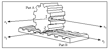 | |
REVOLUTE | Indicates that the joint is a single-degree-of-freedom joint that allows rotation of one part with respect to another about a common axis denoted as zi,j in the figure below. For the REVOLUTE joint, Adams Solver (FORTRAN) superimposes the origins of the I and J markers and keeps their z-axes parallel. Relative motion occurs about the common z-axes. |
Revolute Joint 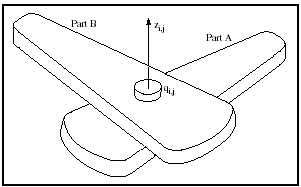 | |
SCREW | Indicates that the joint is a five-degree-of-freedom joint that constrains the translation of the I marker to its rotation (see the figure below). For the SCREW joint, the z-axis of the I marker and the z-axis of the J marker must always be parallel and co-directed. Although the SCREW joint does not enforce this parallelism, the chain of parts and joints that connects the two markers should. During simulation, the I marker displacement along the J marker z-axis is a function of the relative angle of the x-axis of the I marker with respect to the x-axis of the J marker. Adams Solver (FORTRAN) measures a positive rotation according to the right-hand rule. For every full rotation, the displacement of the I marker along the z-axis of the J marker is equal to the value of PITCH. If  is zero, the translational displacement may be zero or any multiple of PITCH. is zero, the translational displacement may be zero or any multiple of PITCH. |
Screw Joint 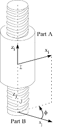 | |
SPHERICAL | Indicates that the joint is a three-degree-of-freedom joint (see the figure below). While permitting all three rotations, a SPHERICAL joint constrains the origins of the I and the J markers to always be superimposed. |
Spherical Joint 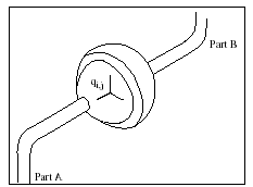 | |
TRANSLATIONAL | Indicates that the joint is a single-degree-of-freedom joint that allows translational displacement of one part relative to another along the common z axes, zi and zj, as shown in the figure below. For the TRANSLATIONAL joint, Adams Solver (FORTRAN) keeps the axes of the I and the J markers parallel and co-directed, and keeps the origin of the I marker on the z-axis of the J marker so that the two markers have a common z-axis. To determine the translational displacement of the I marker with respect to the J marker, Adams Solver (FORTRAN) measures the origin of the I marker with respect to the origin of the J marker along their common z-axis. |
Translational Joint | |
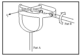
UNIVERSAL | Indicates a two-degree-of-freedom joint that rotates about two axes: the z-axis of the I marker and the z-axis of the J marker (see the figure below). For the UNIVERSAL joint, Adams Solver (FORTRAN) superimposes the origins of the I and J markers and keeps their z-axes perpendicular, so they outline the crosspiece of the joint. The origins of the I and J markers are at the center of the cross. The UNIVERSAL joint functions the same as the HOOKE joint, but uses different marker orientations. |
Universal Joint 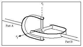 |
Extended Definition
The JOINT statement describes a physically recognizable combination of constraints such as constant-velocity, cylindrical, fixed, Hooke, planar, rack-and-pinion, revolute, screw joints, spherical, translational, and universal (see the figure on the Summary of Joints and the table on joint constraints that follows).
Summary of Joints
Joint Constraints
This type of Joint: | Removes Translational DOF: | Removes Rotational DOF: | Removes Total Number DOF: |
|---|---|---|---|
Constant Velocity | 3 | 1 | 4 |
Cylindrical | 2 | 2 | 4 |
Fixed | 3 | 3 | 6 |
Hooke | 3 | 1 | 4 |
Planar | 1 | 2 | 3 |
Rack-and-pinion | 0.5* | 0.5* | 1 |
Revolute | 3 | 2 | 5 |
Screw | 0.5* | 0.5* | 1 |
Spherical | 3 | 0 | 3 |
Translational | 2 | 3 | 5 |
Universal | 3 | 1 | 4 |
* The rack-and-pinion and screw joints are shown as half translational and half rotational because they relate a translational motion to a rotational motion. They each create one constraint, but the constraint is neither purely translational nor purely rotational.
The reaction force on Part A always acts at the I marker. The reaction force on Part B acts at the instantaneous location of the I marker; that is, the point of application may vary with time. The reaction force on Part B is always equal and opposite to the reaction force on Part A.
The reaction force on Part A always acts at the I marker. The reaction force on Part B acts at the instantaneous location of the I marker; that is, the point of application may vary with time. The reaction force on Part B is always equal and opposite to the reaction force on Part A.
■Joints can be superimposed. Because a joint connects exactly two parts, you can include a part between any two joints you superimpose. In general, if combinations of constraints are to be defined other than those available with the JOINT statement, it is usually simpler to define these combinations with the JPRIM statement.
■The spherical joint that a JOINT statement imposes is identical to the atpoint joint that the JPRIM statement imposes.
■In general, the GEAR statement is easier to use than the JOINT statement to define a rack-and-pinion joint. In addition, the GEAR statement is more accurate. The current RACKPIN joint applies a parasitic rotational force to the rack part. For some models the parasitic rotational force could cause inaccurate results. Learn more information about the GEAR statement.
■The UNIVERSAL and HOOKE joints function identically. One may be more convenient to define than the other, however, depending on the data you have available. If the joint is initially straight, for instance, the HOOKE joint may be defined by two identical markers.
■Functionally, the constant-velocity joint is similar to the UNIVERSAL and HOOKE joints. Connecting two shafts with a constant-velocity joint ensures that the shafts always spin at the same rate, however, unlike the UNIVERSAL and HOOKE joints which cause some fluctuation as the joint bends.
Caution: | ■The two markers that define a joint must be in two different parts. ■Be careful when defining UNIVERSAL and HOOKE joints. In an actual universal joint, if the spin axis of either part comes into alignment with either rotational axis of the joint, the joint can no longer transmit rotational motion. The figure below shows a universal joint in this singular position. In Adams Solver (FORTRAN) the singular position allows the universal joint to spin freely and usually causes simulation failure. |
Universal Joint in the Singular Position
■Be careful when defining CONVEL joints. Whenever the z-axes of the I and J markers in a CONVEL joint become colinear and codirected, the joint is in a singular position. The behavior of the CONVEL joint in the singular position is unpredictable and may be incorrect.
■The screw joint relates the rotational motion of the I marker to the translational motion of the I marker and measures both motions with respect to the J marker. However, the screw joint does not model the backlash or slop that may occur in actual screw joints.
■For both the rack-and-pinion and screw joints, Adams Solver (FORTRAN) positions the I and the J markers at the nearest pitch-multiple position that satisfies the constraint. Examples of pitch multiples of a joint with a pitch value of 2.5 include -5.0, -2.5, 0.0, 2.5, 5.0, etc. Therefore, you should be careful to ensure that the part, marker, and joint information that contributes to the initial positioning of the I marker with respect to the J marker correctly describes the initial position of the I marker.
■If the initial conditions are inconsistent with other conditions in the system, Adams Solver (FORTRAN) varies the part initial positions through an iterative process to correct the inconsistencies and then begins the simulation.
■Use caution when using the initial conditions arguments (IC, ICTRAN, ICROT) in conjunction with a MOTION statement on the same joint. If the MOTION statement and the initial conditions argument(s) specify motion for the same degree of freedom, Adams Solver (FORTRAN) uses the MOTION statement, ignores the initial conditions argument, and issues a warning message.
■If the initial rotational displacement of a revolute or cylindrical joint (as specified by the IC or the ICROT argument on the JOINT statement or by a MOTION statement) varies by anywhere from 5 to 60 degrees from the initial configuration of the joint as indicated by the input positions of the two parts constituting the joint, Adams Solver (FORTRAN) issues a warning message and continues execution. If the variation is greater than 60 degrees, Adams Solver (FORTRAN) issues an error message and stops execution.
■The initial conditions arguments impose constraints that are active only during initial conditions analysis. Adams Solver (FORTRAN) does not impose these initial conditions during subsequent analyses.
■For a kinematic analysis, the initial conditions are redundant. Do not use initial condition arguments on the JOINT statements for systems with zero degrees of freedom.
■Adams Solver (FORTRAN) checks whether axes that are constrained to be parallel or perpendicular are actually close to parallel or perpendicular as input in the dataset. If you input joint markers such that constrained axes are misaligned by more than 5 degrees, Adams Solver (FORTRAN) issues a warning but continues the simulation. If you misalign constrained axes by more than 60 degrees, Adams Solver (FORTRAN) issues an error and stops the simulation. You can input unconstrained axes in any position. In a REVOLUTE joint, for example, Adams Solver (FORTRAN) issues a warning if the angle between the z-axes of the I and J markers is greater than 5 degrees, and an error if the angle is greater than 60 degrees. The x-axes, however, may be at any angle.
Examples
JOINT/0403, UNIVERSAL, I=0406, J=0306
This JOINT statement indicates that Adams Solver (FORTRAN) is to connect one part at Marker 0406 to another part at Marker 0306. Because the statement includes the argument UNIVERSAL, Adams Solver (FORTRAN) uses a universal joint to make the connection.
See other Constraints available.