CLEARANCE
The CLEARANCE statement defines a measure of the distance between two or more geometries or FLEX_BODIES.
Caution: | Clearance Studies are not designed to handle cases where one geometry (I or J) is completely enclosed by the other. Unexpected results can occur. |
Format
CLEARANCE/id, IGEOM=id1[,...,idn]
JGEOM=id2[,...,idn]
IFLEX=id1[,....,idn] [,IREGION=id1[,...,idn],[IEXCLUDE=c1[:...:cn]]
JFLEX=id2[...,idn] [,JREGION=id2[,...,idn],[JEXCLUDE=c2[:...:cn]]
[[,THRESHOLD = distance]]
[]Select one item
[[]] Optionally select the item
Arguments
IGEOM = id | List of geometries id's |
JGEOM = id | List of geometries id's |
IFLEX = id | List of FLEX_BODY id's |
JFLEX = id | List of FLEX_BODY id's |
IREGION/JREGION = id | List matrix id's, the matrix is the list of node id's to include or exclude. Notes: 1. Not specifying the IREGION or JREGION will automatically include all nodes by default. 2. IREGION and JREGION can only be used with Flex Bodies. They define a subset of the nodes on a flex body. Specifying a subset of nodes rather than all nodes, can greatly speed up the Clearance calculation. See Example 2 for more information. |
IEXCLUDE/JEXCLUDE = id | List of booleans to indicate if the nodes indicated by the matrix are to be included or excluded. The default is false so the nodes are included be default. |
THRESHOLD = distance | If the clearance between the bounding box of each geometry is greater than the given THRESHOLD, the clearance between the bounding boxes is computed. If the distance between bounding boxes is smaller than the threshold, or if threshold is set to zero (default), Solve will calculate the clearance between the actual geometries. Setting threshold to a positive nonzero value can speed up simulations when clearances above a threshold do not need to be precise and can be approximated. |
Extended Definition
The clearance statement defines a measure of the distance between two or more geometries or FLEX_BODIES.
The results are written to the XRF results file as XYZ location on the I geometry, XYZ location on the J geometry, the scalar distance between the two points, the id of the I geometry, and the id of J geometry. For FLEX_BODIES it is possible to include or exclude a subset of nodes using the REGION and EXCLUDE lists.
The clearance or one of its components may be referenced in an expression using the following 1D and 3D functions.
ACCCLEAR(cid [,k]) | Relative acceleration of the I and J clearance points |
DCLEAR(cid) | Clearance distance |
IACCCLEAR(cid [,k] | Acceleration of the I clearance point |
IACCCLEARX(cid [,k] [,l]) | X Acceleration of the I clearance point |
IACCCLEARY(cid [,k] [,l]) | Y Acceleration of the I clearance point |
IACCCLEARZ(cid [,k] [,l]) | Z Acceleration of the I clearance point |
ICLEAR(cid) | Adams id of the I graphic/flex body used in the clearance calculation |
IDCLEAR(cid [,k]) | Position of the I clearance point |
IDCLEARX(cid [,k] ) | X Position of the I clearance point |
IDCLEARY(cid [,k]) | Y Position of the I clearance point |
IDCLEARZ(cid [,k]) | Z Position of the I clearance point |
IVCLEAR(cid [,k]) | Velocity of the I clearance point |
IVCLEARX(cid [,k] [,l] ) | X Velocity of the I clearance point |
IVCLEARY(cid [,k] [,l]) | Y Velocity of the I clearance point |
IVCLEARZ(cid [,k] [,l]) | Z Velocity of the I clearance point |
JACCCLEAR(cid [,k]) | Acceleration of the J clearance point |
JACCCLEARX(cid [,k] [,l]) | X Acceleration of the J clearance point |
JACCCLEARY(cid [,k] [,l]) | Y Acceleration of the J clearance point |
JACCCLEARZ(cid [,k] [,l]) | Z Acceleration of the J clearance point |
JCLEAR(cid) | Adams id of the J graphic/flex body used in the clearance calculation |
JDCLEAR(cid [,k]) | Position of the J clearance point |
JDCLEARX(cid [,k] ) | X Position of the J clearance point |
JDCLEARY(cid [,k]) | Y Position of the J clearance point |
JDCLEARZ(cid [,k]) | Z Position of the J clearance point |
JVCLEAR(cid [,k]) | Velocity of the J clearance point |
JVCLEARX(cid [,k] [,l] ) | X Velocity of the J clearance point |
JVCLEARY(cid [,k] [,l]) | Y Velocity of the J clearance point |
JVCLEARZ(cid [,k] [,l]) | Z Velocity of the J clearance point |
VCLEAR(cid [,k]) | Relative velocity of the I and J clearance points |
Where: | |
cid | Is the Adams id of the clearance to measure |
k | The marker in whose coordinate is being calculated. Set k=0 if you the results to be calculated in the global coordinate system. |
l | The reference frame in which the derivative of the vector is taken. Set l=0 if you want the time derivative to be taken in the ground reference frame. |
Example 1
CLEARANCE/5, IGEOM=2, JGEOM=4
CLEARANCE/7, IFLEX=3,9, JGEOM=4
, IREGION=0,2, IEXCLUDE=F:T
Example 2
CLEARANCE/1
, IFLEX = 2
, JFLEX = 3
, IREGION = 4666
, JREGION = 5666
The id's of IREGION and JREGION are MATRIX id's, which are defined as:
Matrix/4666, FULL=CORDER, ROWS=4, COLUMNS=1
, VALUES= 100, 101, 111, 112
Matrix/5666, FULL=CORDER, ROWS=4, COLUMNS=1
, VALUES= 10, 11, 21, 22
The VALUES in each matrix are node id's of Flex Bodies 2 and 3. IREGION specifies the four nodes in the lower right corner of the flex body and JREGION specifies the four nodes in the upper left corner of the flex body. The nodes are shown in Figure 5.
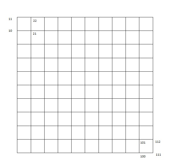
Figure 5 Nodes
One image is used because the geometry of both flex bodies is identical. The Clearance calculation works with the tessellation of the flex bodies. This means that the surface mesh is divided into triangles. It is important to note that a particular node of the flex body can be in more than one triangle.
The actual IREGION and JREGION used in the Clearance calculation are shown Figure 6.
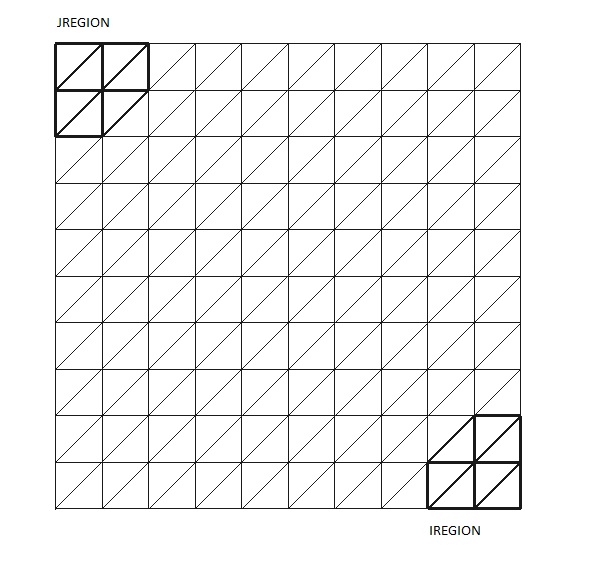
Figure 6 I and J region
Notice that the regions are bigger than one would expect from looking at just the nodes. The reason is that all triangles that touch a node are included in the region. If a user tries to specify just one node in a region, he will actually get three nodes, because the Clearance must work with triangles and it takes three nodes to specify one triangle.
By simulating the flex_clearance model and animating, it can be seen that the Clearance graphic goes from the IREGION on FLEX_BODY/2 to the JREGION on FLEX_BODY/3.