Adams Tire 2D Road Model
This section of the help provides detailed technical reference material for using Adams Tire to define roads along which to maneuver a vehicle. It assumes that you know how to run Adams Car, Adams Solver, or Adams View. It also assumes that you have a moderate level of tire-modeling proficiency.
The 2D Road model lets you model two-dimensional road excitations, including a flat road. Learn about:
2D Road Types
The available road types are:
■DRUM - Tire test drum
■FLAT - Flat road.
■PLANK - Single plank perpendicular, or in oblique direction relative to x-axis, with or without bevel edges.
■POLY_LINE - Piece-wise linear description of the road profile. The profiles for the left and right track are independent.
■POT_HOLE- Single pothole of rectangular shape.
■RAMP - Single ramp, either rising or falling.
■ROOF - Single roof-shaped, triangular obstacle.
■SINE - Sine waves with constant wave length.
■SINE_SWEEP - Sine waves with decreasing wave lengths.
■STOCHASTIC_UNEVEN - Synthetically generated irregular road profiles that match measured stochastic properties of typical roads. The profiles for left and right track are independent, or may have a certain correlation.
Examples of 2D Roads
Sample files for all the road types for Adams Car are in the standard Adams Car database:
install_dir/shared_car_database.cdb/roads.tbl/
Sample files for all the road types for Adams Tire are in:
install_dir/solver/atire/
Note that you must select a specific contact method, such as point-follower or equivalent plane, to define how the roads will interact with the tires. Not all combinations of road, tire, and contact methods are permitted. Allowable combinations are explained in Tire Models help under the description of the specific tire model.
2D Road Model Parameters
The [PARAMETERS] block must contain the following data, some of which are independent of the type of road.
Learn about parameters:
■Drum
■Flat
■Ramp
■Roof
■Sine
Parameters Independent of Road Type
The following parameters are required regardless of the road type.
[PARAMETERS] Independent of Road Type
The parameter: | Indicates: |
|---|---|
offset | A constant shift of the road height values. For a flat road and offset = 0, the road height is zero. |
rotation_angle_xy_plane | Rotation angle of the xy-plane about the road z-axis. In Adams Car, vehicles start running along the negative x-axis by default. It also might be convenient to use positive x-values in the .rdf. In that case, choose rotation_angle_xy_plane = 180 (deg). |
mu | Road friction correction factor (not the friction value itself), to be multiplied with the respective rubber friction values of the tire model. Default setting: mu = 1.0. |
Parameters for Road Type of Drum
The Drum road is supported by all Adams Tire models.
If ROAD_TYPE = drum, then define the following parameters:
[PARAMETERS] for Road Type of Drum
The parameter: | Indicates: |
|---|---|
diameter | Diameter of the tire test drum. When the diameter is < 0, the road model simulates the outer drum. With positive rolling speed, the inner drum will rotate clockwise and the outer drum counter-clockwise. |
v | Rolling speed of drum surface (be sure to keep vehicle at speed zero, otherwise, the wheels move away from the drum). Drum center is located at x = 0. |
number_cleats | Number of extra cleats on drum (number_cleats = 0 allowed). |
cleat_height | Height of extra cleats. |
cleat_starting_angle | Drum angle coordinate of first cleat. |
cleat_length | Length of cleat, measured in circumferential direction of drum. Example of specifying cleat_length. |
cleat_bevel_edge_length | Length of bevel edge of cleat, measured in circumferential direction of drum. Bevel edge has 45° slope. Example of specifying cleat_bevel_edge_length. |
acceleration_time | Optional time span at the beginning of the simulation, during which the drum is accelerated to a nominal rolling speed. |
cleat_direction | Direction of cleat relative to drum spin axis. Direction is zero if cleat is oriented exactly in transversal direction (which is the default case). Direction angle is measured counter-clockwise if looking from above onto the drum surface. Default value = 0 (transversal cleat) |
mu_factor_cleat | Friction modification factor on cleats. |
Parameters for Road Type of Flat
If ROAD_TYPE = flat, then no further parameters are required.
Parameters for Road Type of Plank
If ROAD_TYPE = plank, then define the following parameters:
[PARAMETERS] for Road Type of Plank
The parameter: | Indicates: |
|---|---|
height | Height of plank. |
start | Start of plank (travel distance). |
length | Length of plank, measured along x-axis. |
bevel_edge_length | Length of bevel edge, measured along x-axis. Bevel edge has 45° slope. When bevel_edge_length < 0, rounded corners instead of bevel edges are used. In this case, radius of the corner is |bevel_edge_length|. |
direction | Direction of plank relative to y-axis. If the plank is placed crosswise, direction = 0. If the plank is along the x-axis, direction = 90. |
Parameters for Road Type of Polyline
If ROAD_TYPE = poly_line, then the [PARAMETERS] block must have a (XZ_DATA) subblock. The subblock consists of three columns of numerical data:
■Column one is a set of x-values in ascending order.
■Columns two and three are sets of respective z-values for left and right track.
The following is an example of the full [PARAMETERS] Body for a road type of polyline:
$---------------------------PARAMETERS
[PARAMETERS]
OFFSET = 0
ROTATION_ANGLE_XY_PLANE = 180
$
(XZ_DATA)
0 0 0
1000 100 50
2000 -1000 100
3000 -100 100
3001 50 0
4000 -100 100
The XZ_DATA subblock can be extremely large. In this case, only the portion that is needed at the moment is loaded. To facilitate efficient reloading while simulation is running, do not use any comment lines in a subblock that contains more than 2000 lines.
Parameters for Road Type of Pothole
If ROAD_TYPE = pot_hole, then the parameters are:
[PARAMETERS] Data for Road Type of Pothole
The parameter: | Indicates: |
|---|---|
depth | Depth of pothole. |
start | Start of pothole (travel distance). |
length | Length of pothole. |
Parameters for Road Type of Ramp
If ROAD_TYPE = ramp, then the parameters are:
[PARAMETERS] Data for Road Type of Ramp
The parameter: | Indicates: |
|---|---|
height | Height of ramp. |
start | Start of ramp (travel distance). |
slope | Slope of ramp. 1 means 45°. |
Parameters for Road Type of Roof
If ROAD_TYPE = roof, then the parameters are:
[PARAMETERS] Data for Road Type of Roof
The parameter: | Indicates: |
|---|---|
height | Height of roof (triangle-shaped obstacle). |
start | Start of roof (travel distance). |
length | Length of roof, measured along x-axis. |
Parameters for Road Type of Sine
If ROAD_TYPE = sine, then the parameters are:
[PARAMETERS] Data for Road Type of Sine
The parameter: | Indicates: |
|---|---|
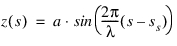
amplitude | Amplitude of sine wave (a). |
wave_length | Wave length of sine wave (  ). ). |
start | Start of sine waves (travel distance) (ss). |
The road height, z, is given by:
Parameters for Road Type of Stochastic Uneven
A stochastic uneven road profile both for left and right wheels is generated, that has properties very close to measured road profiles.
To this end, in a first step discrete white noise signals are formed on the basis of nearly uniformly distributed random numbers, two of these assigned to every 10mm of travel path. The distribution of these random numbers is approximated by summing up several equally distributed random numbers, taking advantage of the 'law of large numbers' of mathematical statistics.
Next, these values are integrated with respect to travel distance, using a simple first order timediscrete integration filter. The reason for not just using a pure integrator is to cut off extremely low frequencies, which would result in large road elevation values, not at all affecting vehicle dynamics.
The independent variable of that filter is not time, but travel path. That is why the filter cut-off frequency Ωc is controlled by a 'path constant' S = 1/Ωc instead of a time constant. Approximate power spectral density (PSD) of this road surface profile is given by
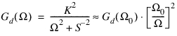 ,
,S >> 1m
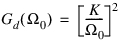
The filter process results in two realizations of this approximate 'white velocity noise'; that means, two signals, the derivatives of which are close to white noise. Signals with that property are known as road profiles with 'waviness' w = 2 (cf. ISO 8608). Several investigations show that the waviness derived from measured road displacement PSDs ranges from about 1.8 to 2.2. The reference spectral density value Gd(Ω0), with Ω0 = 1 rad/m, is used in ISO 8608 to classify road surface profiles, according to the following table:
Road class | Gd(Ω0)[10−6 m3] | ||
|---|---|---|---|
min. value | mean value | max. value | |
A | - | 1 | 2 |
B | 2 | 4 | 8 |
C | 8 | 16 | 32 |
D | 32 | 64 | 128 |
E | 128 | 256 | 512 |
F | 512 | 1024 | 2048 |
G | 2048 | 4096 | 8192 |
H | 8192 | 16384 | - |
The last step in the generation of the stochastic uneven road profiles is to linearly combine the two realizations z1(s), z2(s) of the above mentioned process, resulting in the left and right profile zl (s), zr (s). This is done such that these two signals are completely independent, if correlation_rl = 0.0, and identical, if correlation_rl = 1.0:
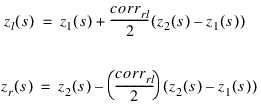 .
.If ROAD_TYPE = stochastic_uneven, then the parameters are:
[PARAMETERS] for Road Type of Stochastic Uneven
The parameter: | Indicates: |
|---|---|
reference_spectral_density | Gd(Ω0) in m3 |
ISO_8608_road_class | ISO 8608 road class, according to table above. Mean Gd(Ω0) value of the respective class will be used, possible values A or B or ... H |
path_constant | 'path constant' S to control high-pass integration filter cut-off frequency in path domain. Parameter is optional, default value is 1000 m |
correlation_rl | Variable to control correlation between left and right track: ■If 0, no correlation. ■If 1, complete correlation (that is, left track = right track). Any value between 0 and 1 is allowed. |
Note: | Either the keyword reference_spectral_density or ISO_8608_road_class should be defined in the road property file |
Parameters for Road Type of Sweep
If ROAD_TYPE = sine_sweep, then the parameters are:
[PARAMETERS] Data for Road Type of Sine Sweep
The parameter: | Indicates: |
|---|---|
start | Start of swept sine wave (travel distance) (  ). ). |
end | End of swept sine wave (travel distance) (  ). ). |
amplitude_at_start | Amplitude of swept sine wave at start travel distance (  ). ). |
amplitude_at_end | Amplitude of swept sine wave at end travel distance (  ). ). |
wave_length_at_start | Wave length of swept sine wave a start travel distance (  ). ). |
wave_length_at_end | Wave length of swept sine wave at end travel distance. Must be less than or equal to wave_length_at_start (  ). ). |
sweep_type | ■sweep_type = 0: frequency increases linearly with respect to travel distance. ■sweep_type = 1: wave length decreases by a constant factor per cycle. Depending on the value of sweep_type, the road height is given by the following functions, where 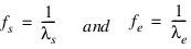 ■Linear sweep: (sweep_type = 0) The frequency increases linearly with respect to travel distance. The road height value z(s) as function of travel distance s is calculated as follows: 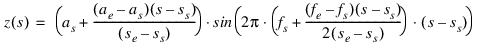 Note the factor 2 in the denominator is not an error. The actual frequency (= derivative of the sine function argument with respect to travel path, divided by  ; this is not equal to that factor that is multiplied by ; this is not equal to that factor that is multiplied by in the sine function) is given by the following: in the sine function) is given by the following: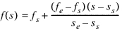 ■Logarithmic sweep: (sweep_type = 1) with every cycle, the wave length decreases by a constant factor. The road height value is calculated as follows: 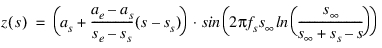 where 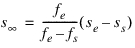  is the travel path where theoretically an infinitely high frequency was reached, measured relative to sweep start is the travel path where theoretically an infinitely high frequency was reached, measured relative to sweep start  . The actual frequency is given by: . The actual frequency is given by: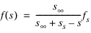 |
Graphics
For visualization of the 2D road, one can specify the size of the road and the number of grid points in the [GRAPHICS] section of the road property file.
LENGTH and WIDTH determine the length (along x) and width respectively of the visualized road section. With the LENGTH_SHIFT and WIDTH_SHIFT the position of the section can be positioned. The NUM_LENGTH_GRIDS and NUM_WIDTH_GRIDS determine the number of grid points in longitudinal and lateral direction.
Example:
[GRAPHICS]
LENGTH = 50000.0
WIDTH = 5000.0
NUM_LENGTH_GRIDS = 500
NUM_WIDTH_GRIDS = 50
LENGTH_SHIFT = 45000.0
WIDTH_SHIFT = 0.0
Road Repositioning
The position and orientation of the road can be changed by defining the reference system in the optional [REFSYS] block:
Keyword: | Description: |
|---|---|
OFFSET | Three values, respectively the translational offset value in longitudinal direction, the translational offset value in lateral direction and the translational offset value in vertical direction, all default 0. |
ROTATION_ANGLE_XY_PLANE | The rotational offset around the Z-axis, default 0. |
In the TeimOrbit formatted road property file, this section will list as follows:
$-------------------------------------------------------------refsys
[REFSYS]
OFFSET = 1.0 0.0 0.3
ROTATION_ANGLE_XY_PLANE = 25.0
Road Normal calculation
The road normal setting of 2D Road is upwards by default. If one would need to include the effect of the road height changes, following environment variable needs to be set:
MSC_ADAMS_TIRE_OBSTACLE_NORMAL=YES