About Axis Systems and Sign Conventions
The following sections describe the tire axis systems and the sign conventions for tire kinematic and force outputs.
Tire Axis Systems
The following sections describe the ISO coordinate systems to which Adams Tire conforms. The ISO coordinates are shown as follows:
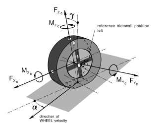
ISO-C (TYDEX C) Axis System
The TYDEX STI specifies the use of the ISO-C axis system for calculating translational and rotational velocities, and for outputting the force and torque at the tire hub.
The properties of the ISO-C axis system are:
■The origin of the ISO-C axis system lies at the wheel center.
■The + x-axis is parallel to the road and lies in the wheel plane.
■The + y-axis is normal to the wheel plane and, therefore, parallel to the wheel’s spin axis.
■The + z-axis lies in the wheel plane and is perpendicular to x and y (such as z = x x y).
TYDEX-C Axis System Used in Adams Tire
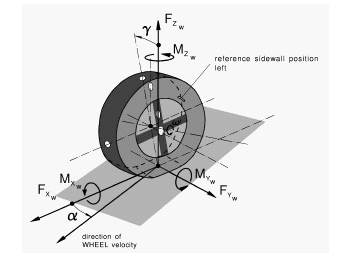
ISO-W (TYDEX W) Contact-Patch Axis System
The properties of the ISO-W (TYDEX W) axis system are:
■The origin of the ISO-W contact-patch system lies in the local road plane at the tire contact point.
■The + x-axis lies in the local road plane along the intersection of the wheel plane and the local road plane.
■The + z-axis is perpendicular (normal) to the local road plane and points upward.
■The + y-axis lies in the local road plane and is perpendicular to the + x-axis and + z-axis (such as y = z x x).
TYDEX W-Axis System Used in Adams Tire
Road Reference Marker Axis System
The road reference marker axis system is the underlying coordinate system that Adams Tire uses internally. For example, the tire translational displacement and local road normal for a three-dimensional road are expressed in the axis system of the road reference marker.
The properties of the reference marker axis system are:
■The GFORCE reference marker defines the axis system.
■The + z-axis points upward.
About Tire Kinematic and Force Outputs
Adams Tire calculates the kinematic quantities of slip angle, inclination angle, and longitudinal slip. These are based on the location, orientation, and velocity of the tire relative to the road. In turn, Adams Tire calculates the forces and moments of the tire using the tire kinematics as inputs to the tire mode you select.
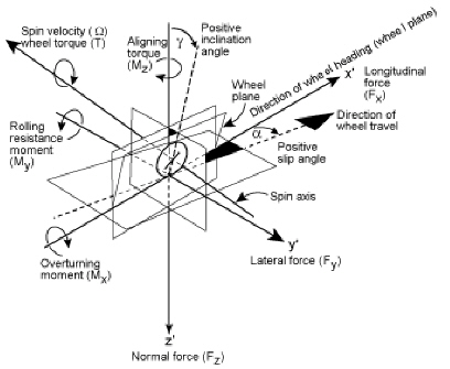
Sign Conventions for Tire Outputs
The table below, Conventions for Naming Variables, and the figure, ISO Coordinate System, show the sign conventions for tire kinematic and force outputs.
Conventions for Naming Variables
Variable name and abbreviation: | Description: | |
|---|---|---|
Slip angle |  | The angle formed between the direction of travel (velocity) of the center of the tire contact patch and the ISO-W: x-axis. If the wheel-travel direction has a component in the ISO-W: +y direction, a is positive. This produces a negative lateral force (Fy). Note that the steer angle, or the vehicle attitude angle, plays no part in defining the slip angle. |
Inclination angle |  | The angle formed between the ISO-W: x-z plane and the wheel plane. If the wheel plane has a component lying in the direction of ISO-W, the inclination angle is positive. |
Longitudinal slip |  (ωactual-ωfree)/ωfree | The ratio of the longitudinal-slip velocity of the contact patch to the longitudinal velocity of the wheel. The longitudinal slip is positive during acceleration of a moving tire and negative during braking. Longitudinal slip is limited to the range -1 to +1. |
Longitudinal force at contact patch | Fx | The x-component of the force exerted by the road or tire. |
Lateral force at contact patch | Fy | The y-component of the force exerted by the road or tire. Lateral force may be produced by one or any combination of the following: slip angle, inclination angle, conicity, or plysteer. |
Normal force at contact patch | Fz | The z-component of the force exerted by the road or tire. The direction of this force is up. |
Overturning moment at contact patch | Mx | The moment of the forces at the contact patch acting on the tire by the road with respect to the ISO-W: x-axis. |
Rolling resistance moment | My | The moment of the forces at the contact patch acting on the tire by the road with respect to the y-axis. |
Aligning moment | Mz | The moment of the forces at the contact patch acting on the tire by the road with respect to the z-axis. |
Spin axis | Spin Axis | The axis about which the wheel rotates. Perpendicular to the wheel plane, not necessarily about the ISO-C: y-axis (only if inclination angle is zero). |
The central plane of the tire and wheel | Wheel plane | The wheel plane is normal to the wheel spin axis. |
Wheel heading along road | ISO W:X | This is not the same as the direction in which the wheel is traveling. If the tire reverses its direction, the axis system flips 180 degrees about the z'-axis. |
Direction to the left along the road | ISO W:Y | The direction to the left along ground as viewed from behind a forward rolling tire. Expressed as right-hand orthogonal to the definitions of x' and z' (such as y = Z x X). |
Z-coordinate | ISO W:Z | Perpendicular to the road in the neighborhood of the origin of the tire axis system in a positive (downward) direction. (If the road is flat and in the x-y plane, this is negative global z.) |
ISO Coordinate System
SAE Coordinate System
When comparing the slip quantities, angles, forces and torques defined in ISO with respect to the SAE coordinate system, the following variables change sign:
ISO | SAE | ||
|---|---|---|---|
 | = |  | Longitudinal slip |
 | = | -  | Slip angle |
 | = |  | Inclination angle |
Fx | = | Fx | Longitudinal force |
Fy | = | -Fy | Lateral force |
Fz | = | -Fz | Vertical load |
Mx | = | Mx | Overturning Moment |
My | = | -My | Rolling resistance Moment |
Mz | = | -Mz | Aligning Moment |