Using the Soft-Soil tire model
The Adams Tire Soft Soil tire model offers a basic model to describe the tire-soil interaction forces for any tire on elastic/plastic grounds, such as sand, clay, loam and snow.
The model requires a tire property file with keyword SOFT-SOIL and a road data file (one of the existing formats) with additional soil properties. Two tire-soil contact models are offered:
■Elastic-plastic soil deformation model with tire deflection, USE_MODE = 1
■Visco-elastic soil deformation model, USE_MODE = 2
■Elastic-plastic soil deformation model with a rigid wheel, USE_MODE = 3
Definition of Tire Slip Quantities
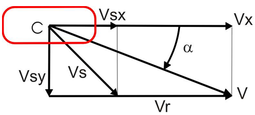
Figure 1 Definition of the slip velocities in the tire-road contact point
The longitudinal slip velocity Vsx in the SAE-axis system is defined using the longitudinal speed Vx, the wheel rotational velocity  , and the effective rolling radius Re:
, and the effective rolling radius Re: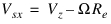 | (1) |
The lateral slip velocity is equal to the lateral speed in the contact point with respect to the road plane:
 | (2) |
The slip quantities  (longitudinal slip) and
  (slip angle) are calculated with these slip velocities in the contact point, for negative Vsx they are defined as:
(longitudinal slip) and (slip angle) are calculated with these slip velocities in the contact point, for negative Vsx they are defined as: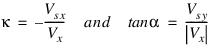 | (3) |
and for positive Vsx (driving) as:
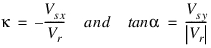 | (4) |
Vr is the rolling speed Vr is determined using the effective rolling radius Re: 
Note that for realistic tire forces the slip angle  is limited to
  degrees and the longitudinal slip
  to
to  .
.
is limited to degrees and the longitudinal slip to .Loaded and Effective Tire Rolling Radius
The loaded rolling tire radius Rl is defined as the unloaded tire radius R0 minus the tire deflection f0 due to the vertical load:
 | (5) |
The effective rolling radius Re (at free rolling of the tire), which is used to calculate the rotational speed of the tire, is defined by:
 | (6) |
For radial tires, the effective rolling radius is rather independent of load in its load range of operation because of the high stiffness of the tire belt circumference. Only at low loads does the effective tire radius decrease with increasing vertical load due to the tire tread thickness, see the Figure 2.
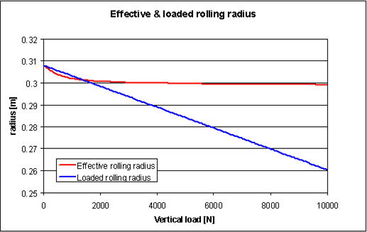
Figure 2 Effective and loaded tire radius as a function of the vertical load
Effective Rolling Radius and Longitudinal Slip
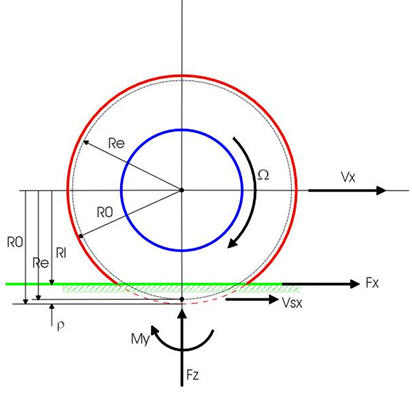
Figure 3 Side view of a rolling tire
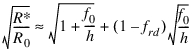
To represent the effective rolling radius Re, a PAC2002 compatible equation is used:
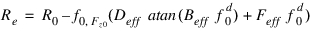 | (8) |
in which  is the nominal tire deflection at the nominal tire load Fz0:
is the nominal tire deflection at the nominal tire load Fz0: | (9) |
and  is called the dimensionless radial tire deflection, defined by:
is called the dimensionless radial tire deflection, defined by: | (10) |
Elastic-plastic tire-soil contact
The interaction forces for a rigid wheel (use_mode = 3)
The static sinkage of a rigid object into a soft soil depends on the load on that object: Bekker [1] formulated the sinkage h of a flat plate with width b as follows:
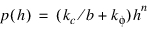 | (11) |
in which  and
and  are the cohesive and frictional moduli respectively, n the sinkage exponent. The static stress p is in equilibrium with the vertical force Fz.
and are the cohesive and frictional moduli respectively, n the sinkage exponent. The static stress p is in equilibrium with the vertical force Fz. 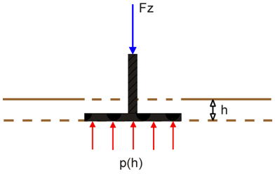
Figure 4 Pressure distribution under a flat plate
When applying this approach to a non-rolling wheel the static stress distribution can be estimated as shown in the Figure 5
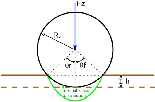
Figure 5 Static stress distribution under a non-rolling rigid wheel
For the dynamic sinkage the wheel rotational speed  must be taken into account.
must be taken into account. 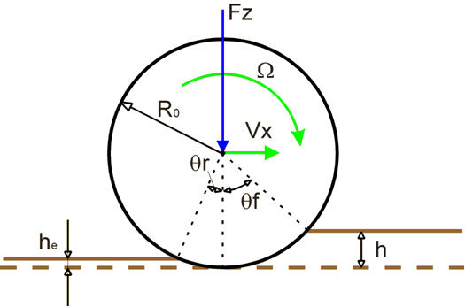
Figure 6 Wheel entry and exit angle when rolling on soil
Assume a wheel − soil contact with entry angle  and exit angle
  , see also [2], then these angles can be written as a function of the total sinkage h and the exit penetration he as follows:
and exit angle , see also [2], then these angles can be written as a function of the total sinkage h and the exit penetration he as follows: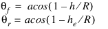 | (12) |
The exit penetration he depends on the elastic stiffness Cs of the soil.
Based on the terramechanical approach as described in [2] the normal and shear stresses can be modeled as shown in the Figure 7.
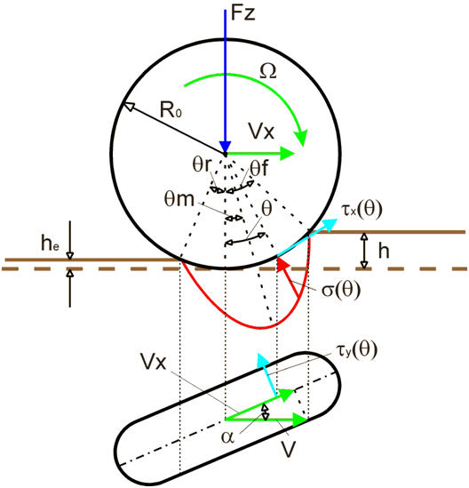
Figure 7 Normal and shear stress modelling of a rotating wheel
The wheel normal stress distribution  can be defined as function of the wheel angle
  [2,3]:
can be defined as function of the wheel angle [2,3]:for  :
:
: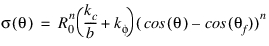 | (13) |
for  :
:
: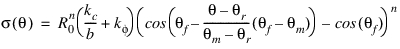 | (14) |
with b the wheel width and R0 the wheel radius.
The angle  is the angle at which the maximum normal stress
  occurs [4]:
is the angle at which the maximum normal stress occurs [4]: | (15) |
The shear stress [5,6] in longitudinal direction is:
 | (16) |
and in lateral direction yields:
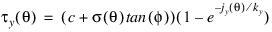 | (17) |
In equations 15 and 16 c represents the cohesion stress of the soil,  the friction angle of the soil and kx and ky the shear deformation moduli. Assuming that the wheel has a longitudinal slip
  , the longitudinal shear displacement along the contact area jx in equation 16 can be estimated [5,6] by using the longitudinal slip
  and wheel radius R0:
the friction angle of the soil and kx and ky the shear deformation moduli. Assuming that the wheel has a longitudinal slip , the longitudinal shear displacement along the contact area jx in equation 16 can be estimated [5,6] by using the longitudinal slip and wheel radius R0: | (18) |
Similar the lateral shear displacement jy will depend on the slip angle  and the wheel radius R0:
and the wheel radius R0: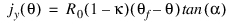 | (19) |
Figure 8 illustrates the shear stress as a function of soil deformation.
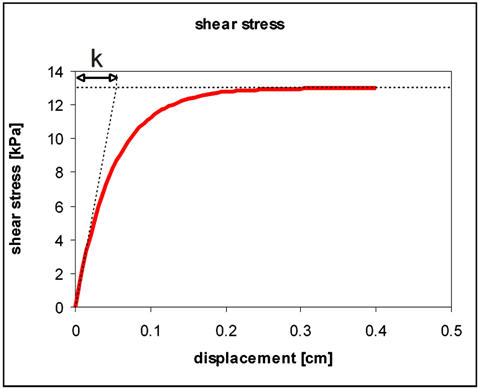
Figure 8 Measured shear stress compared to fitted stress (equation 15)
The longitudinal shear deformation modulus kx is defined as:
 | (19) |
And the lateral shear deformation modulus ky:
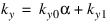 | (20) |
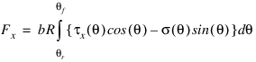
Having the normal and shear stress for the rotating wheel, the tire-soil interaction contact forces and moments can be calculated:
■Longitudinal force:
(21)
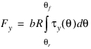
■Lateral force:
(22)
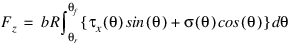
■Vertical load:
(23)
■The overturning moment in the contact point is estimated by calculating the moment of the vertical load times the lateral tire deflection using half the vertical tire stiffness:
(24)
■Rolling resistance moment:
(25)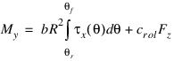
with crol the tire (internal) rolling resistance coefficient.
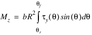
■Aligning moment:
(26)
Bulldozing resistance
Bulldozing resistance is a resistance force generated by the bulldozed soil of a rotating or a steered wheel on soft or loose soil. Several estimation methods have been developed based on the soil mechanics and geotechnical principle, in this model the Hegedus's estimation [14] method will be used.
This method assumes that a vertical blade with a certain width pushes soil, followed by a bulldozing resistance generated by the pushed soil. By pushing the blade, a linear destructive phase form will be assumed and swollen soil will be generated.
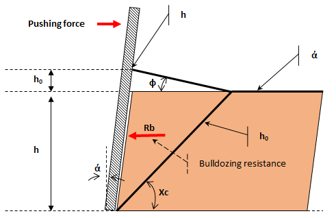
Figure 9 The Hegedus's estimation method
The upper Figure 9 shows the Hegedus's estimation method, where the destructive angle (Xc) is located between the soil horizontal level and the linear destructive phase. In addition, this estimation approach takes the swollen soil into account by calculating it geometrically;
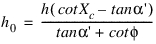 | (27) |
 | (28) |
Where  is the angle of the blade in the approach and Rb is the bulldozing resistance; for a tire
  is equal to the camber angle.
is the angle of the blade in the approach and Rb is the bulldozing resistance; for a tire is equal to the camber angle. 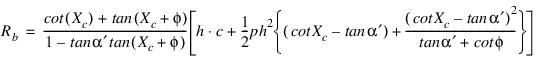 | (29) |
In which p is the soil density.
As mentioned before, the bulldozing force (Fs) can be obtained by integrating the bulldozing resistance along the wheel-soil contact patch.
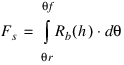 | (30) |
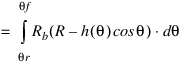 | (31) |
Then, the total lateral force will be calculated with:
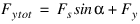 | (32) |
Tire deformation (usemode = 1)
In order to take the tire deflection into account the substitution circle approach is taken as was suggested by Bekker [7]:
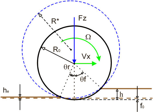
Figure 10 Substitution circle to account for tire deflection
At a certain penetration of the tire into the soil the tire deflection and sinkage can be determined by an iteration process based on the fact that the vertical tire force and the force due to the sinkage must be equal.
The tire force can be calculated with the tire stiffness Cz and tire deflection f0 by:
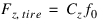 | (33) |
while the tire sinkage force is defined by equation (22), however, replacing the unloaded tire radius R0 by the radius of the substitution circle R*.
Bekker [7] derived following relation in between the tire deflection f0 and tire sinkage h:
 | (34) |
With this Bekker substitution circle method, the wheel radius R0 in the upper equations 13, 14, 18, 19, 21-26 is replaced by the substitution radius R* for taking the tire deflection into account (usemode = 1). The factor frd can reduce the effect of the substitution circle, by default the value is 1 (100% reduction).
Elastic and Plastic deformation
Depending on the soil properties one part of the deformation is elastic and the remaining part is non-irreversible (plastic deformation). The elastic deformation is calculated with by the soil stiffness Cs at the maximum normal stress  :
:
: | (35) |
When setting Cs to zero, the elastic deformation will be neglected.
Multi-pass effect
When a tire has passed a certain spot of soil, a second tire will experience different soil properties when rolling over that spot due to the plastic deformation of the soil by the first tire.
Therefore this Soft Soil tire model stores the elastic and plastic deformation of each tire as a function of the contact point x, y coordinates. When a tire passes a point with plastic deformation caused by a previous tire, the normal pressure calculation will account for the plastic deformation history.
Figure 11 explains the mechanism applied in this tire model [8]:
Assume two tires rolling after each other over the same spot of soil. The first tire will have a total deformation h1 existing of a plastic part hp1 and an elastic part he1. When a second tire passes the same spot, the soil will first have an elastic deformation from A to B (= he1) and then continue to follow the normal pressure characteristic to point C. The plastic deformation of the second tire hp2 will be equal to the total deformation h2 subtracted with the elastic deformation he2.
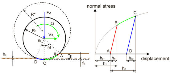
Figure 11 Normal pressure characteristic for multi-pass approach
The tire model stores the x, y coordinates, the elastic and plastic deformation and tire width of each tire. Because of the one-point of contact approach used in this Soft-Soil tire model, the total stored plastic deformation will be applied for a next tire when its contact point comes into the rut of a previous tire.
When setting the keyword MULTIPASS in the [MODEL] section of the tire property file, the multi-pass effect can be switched on:
MULTIPASS = 'YES'
By default the track of the tire itself will not be taken into account. Though if a tire would pass his own path and that compaction effect should be accounted for as well, following keyword must be set in addition:
BACK_FORTH_EFFECT = 'YES'
The compressed soil history can be stored in a binary file by setting following keyword in the [SOIL_PROPERTIES] section of the road property file:
SOIL_HISTORY_STORAGE_FILE = '<filename>'
The soil history can be re-used by adding the following keyword in the [SOIL_PROPERTIES] section of the road property file:
USE_SOIL_HISTORY_FILE= '<filename>'
Transient tire response
When rolling, a tire requires some response time to react on instantaneous changes of the tire - soil contact. In order to account for this tire lag and to improve the tire behavior at low speed, a linear transient model as described in [13] has been added.
The transient tire behavior can be switched on using the keyword TRANSIENT in the [MODEL] section of the tire property file:
TRANSIENT = 'YES'
Also the relaxation length in longitudinal and lateral direction (independent of load and slip) can be defined:
[PARAMETER]
REL_LEN_LON = 0.3
REL_LEN_LAT = 0.3
Visco-elastic tire-soil contact
Next to elastic-plastic deformation models for soft soil, also visco-elastic modeling approaches exist. Wanjii e.o. [9] derived a visco-elastic model for the normal stress along the contact line in between the tire and the soil. A three element Maxwell approach is used for a rigid wheel, see Figure 12.
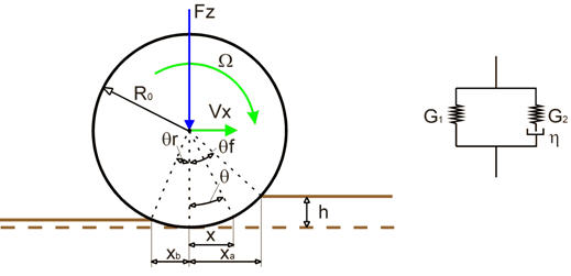
Figure 12 Three element Maxwell model for a rigid wheel on visco-elastic soil
For this model the normal stress in the contact in between tire and ground is:
 | (36) |
With


In which
■Tr is the relaxation time
■ is the viscosity of the soil
is the viscosity of the soil■Vx is the forward velocity of the tire
■G1 is the first elastic modulus
■G2 is the second elastic modulus
The longitudinal and lateral shear stresses are calculated using the equations 15 until and including 19 as used for the elastic-plastic tire-soil model. Similar for the tire-ground interaction forces equation (20 - 24) are used.
For the multi-pass effect, the road deformation at the exit of the tire-soil contact (point B) and the time of deformation occurrence is stored. When a second tire passes the same spot, the road deformation corrected with the relaxation effect is taken to correct the road height input.
References:
1. Bekker, M.G., Off-the-road-locomotion, Ann Arbor, The University of Michigan Press, 1960.
2. G. Ishigami, A. Miwa, K. Nagatani, K. Yoshida, Terramechanics - Based Model for Steering Maneuver of Planetary Exploration Rovers on Loose Soil, Journal of Field robotics 24(3), 233-250 (2007), Wiley Periodicals, Inc.
3. Yoshida, K., Watanabe, T., Mizuna, N., Ishigami, G., Terramechanics - based analysis and traction control of a lunar/planetary rover. In Proceedings of the Int. Conf. Of Field and Service Robotics (FSR '03), Yamanashi, Japan.
4. Wong, J.Y., Reece, A., Prediction of rigid wheel performance based on the analysis of soil-wheel stresses part I, performance driving rigid wheels, Journal of Terramechanics, 4, 81-98.
5. Janosi, Z. Hanamoto, B., The analytical determination of drawbar pull as a function of slip for tracked vehicle in deformable soils, In proceedings of the 1st Int. conf. on Terrain-Vehicle systems, Torino, Italy.
6. Wong, J.Y., Theory of Ground Vehicles, John Wiley & Sons, Inc., second edition, 1993.
7. Bekker, M.G., Introduction to terrain-vehicle systems, Ann Arbor, The University of Michigan Press, 1969.
8. AS2TM User's Guide, version 1.12, AESCO GbR, Hamburg.
9. S. Wanjii, T. Hiroma, Y. Ota, T. Kataoka, Predicition of Wheel Performance by Analysis of Normal and Tangential Stress Distributions under the Wheel-Soil Interface, Journal of Terramechanics, Vol. 34, No. 3, pp. 165-186, 1997.
10. Schmid, I.C., Interaction of Vehicle and Terrain Results from 10 Years Research at IKK, Journal of Terramechanics, Vol. 32, No. 1, pp. 3-26, 1995.
11. Schmid, I.C., Aubel, Th., Der elastische Reifen auf nachgiebiger Fahrbahn - Rechenmodell im Hinblick auf Reifendruckregelung, VDI Berichte nr. 916, 1991.
12. Faßbender, F., Simulation der Vertikaldynamik von Fahrzeugen auf Geländeböden mit STINA - SOIL TIRE INTERFACE TO ADAMS einem Zusatzmodul für das Mehrkörperprogramm ADAMS. Number 521 in Fortschritt-Berichte VDI Reihe 12. VDI Verlag, Düsseldorf, 2002. Dissertation Universität der Bundeswehr Hamburg.
13. H.B. Pacejka, Tyre and Vehicle Dynamics, 2002, Butterworth-Heinemann, ISBN 0 7506 5141 5.
14. E. Hegedus, "A simplified method for the determination of bulldozing resistance," Land Locomotion Research Laboratory, Army Tank Automotive Command Report, vol. 61, 1960.
Feature and property overview of the Adams Tire Soft Soil Tire model
■Two tire-road contact models:
■Elastic-plastic contact model
♦rigid wheel or flexible tire
♦multi-pass effect: road plastic deformation history is stored and taken into account when another tire passes the same spot
■Visco-elastic contact model
♦rigid tire: no tire deflection
♦multi-pass effect: road viscous deformation is stored. The stored deformation reduced by the relaxation effect is taken into account when another tire passes the same spot
■Tire effective rolling radius is defined similar to pac2002 tire model
■Tire properties are very basic (tire vertical stiffness and damping, unloaded radius, width and effective rolling radius parameters)
■The existing Adams Tire roads can be used, just an additional section with the soil properties is required. These soil properties are valid for the whole road.
■Linearization of  - Fx characteristic during q-statics to ensure robust q-statics
- Fx characteristic during q-statics to ensure robust q-statics■Linear vertical tire stiffness can be replaced by a (non-linear) deflection-load curve
■Scaling factors of road friction, tire cornering and longitudinal stiffness' are supported
■SMP (multi-thread, C++ solver) is supported
■Tire-road contact is a one-point contact. The tire force in the contact point results from the tire normal and shear stress calculated along the predicted contact line.
Specific requests for the Soft-Soil Tire Model
Output: | REQTYP Request: | Component definitions: |
|---|---|---|
Tire sinkage and soil deformation | 15 | x = plastic sinkage (in case of the plastic-elastic model, h-he) y = elastic sinkage (he) z = viscous sinkage (in case of the visco-elastic model, h-he) r1 = stored plastic deformation of the road from a previous tire (multipass) r2 = stored elastic deformation of the road from a previous tire (multipass) r3 = stored viscous deformation of the road from a previous tire (multipass) Note: The total sinkage is the sum of the plastic/viscous sinkage and the elastic sinkage |
Tire soil contact stress info | 16 | x = contact entry angle (θf) y = contact exit angle (θr) z = angle with max normal stress (θm) r1 = max normal stress (σm) r2 = max shear stress in longitudinal direction (τx) r3 = max shear stress in lateral direction (τy) |
Tire deflection and radii | 17 | x = tire deflection (f0) y = tire loaded rolling radius (Rl) z = tire effective rolling radius (Re) r1 = substitution radius (R*) |
Example of an Adams Dataset section with these requests:
REQUEST/1
, CUNITS = "no_units", "length", "length", "length", "no_units", "length"
, "length", "no_units"
, CNAMES = "", "z_plastic", "z_elastic", "z_visco", "", "z_plastic_road"
, "z_elastic_road", "z_visco_road"
, RESULTS_NAME = front_tire_deform
, FUNCTION = USER(902, 15, 1)\
, ROUTINE = abgTire::req902
!
REQUEST/2
, CUNITS = "no_units", "angle", "angle", "angle", "no_units", "pressure"
, "pressure", "pressure", "no_units"
, CNAMES = "", "entry_angle", "exit_angle", "max_stress_angle", ""
, "max_normal_stress", "max_x_shear_stress", "max_y_shear_stress"
, RESULTS_NAME = front_tire_stress
, FUNCTION = USER(902, 16, 1)\
, ROUTINE = abgTire::req902
!
REQUEST/3
, COMMENT = soft soil: tire kinematics and substitution radius and sinkage
, CUNITS = "no_units", "length", "length", "length", "no_units"
, "angular_velocity", "length", "length"
, CNAMES = "", "tire_deflection_front", "loaded_radius_front"
, "rolling_radius_front", "", "rotational_velocity_front"
, "substitution_radius_front", "total_sinkage_front"
, RESULTS_NAME = tir_wheel_soft_soil_states
, FUNCTION = USER(902, 17, 1)\
, ROUTINE = abgTire::req902
Example of the tire property file for the Soft-Soil Tire model:
$---------------------------------------------------------MDI_HEADER
[MDI_HEADER]
FILE_TYPE = 'tir'
FILE_VERSION = 2.0
FILE_FORMAT = 'ASCII'
(COMMENTS)
{comment_string}
'Tire - XXXXXX'
'Pressure - XXXXXX'
'Test Date - XXXXXX'
'Test tire'
'New File Format v2.1'
$--------------------------------------------------------------units
[UNITS]
LENGTH = 'mm'
FORCE = 'newton'
ANGLE = 'degree'
MASS = 'kg'
TIME = 'sec'
$--------------------------------------------------------------model
[MODEL]
! use mode 1 2 3
! ---------------------------------------------------------------
! flexible wheel/tire with elastic-plastic road X
! rigid wheel/tire with visco-elastic road X
! rigid wheel/tire with plastic-elastic road X
!
PROPERTY_FILE_FORMAT = 'SOFT-SOIL'
USE_MODE = 1.0
MULTIPASS = 'NO'
TRANSIENT = 'NO'
BACK_FORTH_EFFECT = 'NO'
!
!This parameter reduces the effect of the substitution circle to accout for
!the tire flexibility (use mode = 3)
! value 0: no reduction
! value 1: max reduction (default)
!
!SUBST_RAD_REDUCTION = 1
$----------------------------------------------------------dimension
[DIMENSION]
UNLOADED_RADIUS = 309.9
WIDTH = 235.0
ASPECT_RATIO = 0.45
$----------------------------------------------------------parameter
[PARAMETER]
NOMINAL_TIRE_LOAD = 4000
VERTICAL_STIFFNESS = 310.0
VERTICAL_DAMPING = 1.5
ROLLING_RESISTANCE = 0.01
BREFF = 8.4
DREFF = 0.27
FREFF = 0.07
$--------------------------------------------------------------shape
[SHAPE]
{radial width}
1.0 0.0
1.0 0.2
1.0 0.4
1.0 0.5
1.0 0.6
1.0 0.7
1.0 0.8
1.0 0.85
1.0 0.9
0.9 1.0
$---------------------------------------------------------load_curve
$ For a non-linear tire vertical stiffness
$ Maximum of 100 points
![DEFLECTION_LOAD_CURVE]
!{pen fz}
!0 0.0
!1.0 212.0
!2.0 428.0
!3.0 648.0
!5.0 1100.0
!10.0 2300.0
!20.0 5000.0
!30.0 8100.0
Example of the required Soil properties in the Road Data File:
Existing road data files can be used, but a 'SOIL_PROPERTIES' section has to be added:
$-----------------------------------------------------SOIL_PROPERTIES
[SOIL_PROPERTIES]
SOIL_HISTORY_STORAGE_FILE = 'soil_history.bin '
! USE_SOIL_HISTORY_FILE= 'soil_history.bin '
FRICTION_ANGLE = 37.2 $units: degree
COHESION_STRESS = 8.0E-4 $units: N/mm**2
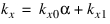
SOIL_DEFORM_MOD_KX0 = 0.751 $units: mm/deg
SOIL_DEFORM_MOD_KX1 = 36 $units: mm
SOIL_DEFORM_MOD_KY0 = 0.349 $units: mm/deg
SOIL_DEFORM_MOD_KY1 = 13.0 $units: mm
!visco-elastic tire:
ELASTIC_MODULUS_G1 = 0.071E-3 $units: N/mm**3
ELASTIC_MODULUS_G2 = 1.072E-3 $units: N/mm**3
SOIL_VISCOSITY = 7.14E-3 $units: Ns/mm**3
!plastic-elastic tire:
PRESSURE_SINKAGE_KC = 1.37E-3 $units: N/mm**(n+1)
PRESSURE_SINKAGE_KFI = 8.14E-4 $units: N/mm**(n+2)
SINKAGE_EXPONENT = 1 $units: = n
SOIL_INTERACTION_A0 = 0.4 $units: -
SOIL_INTERACTION_A1 = 0.15 $units: -
SOIL_STIFFNESS = 8.14E-3 $units: N/mm**3
SOIL_DENSITY = 16E-6 $units: kg/mm**3
Note: | A library of soil properties for different types of soil has been exposed in the technical article KB8022027 at SimCompanion. |
Symbols
Beff | effective rolling radius factor |
b | tire/wheel width |
c | cohesion |
crol | tire rolling resistance coefficient |
Deff | effective rolling radius factor |
Cz | tire vertical stiffness |
Cs | soil stiffness |
f0 | tire deflection |
 | dimensionless tire deflection |
 | nominal tire deflection |
G1 | elastic modulus |
G2 | elastic modulus |
Feff | effective rolling radius factor |
Fx | longitudinal force |
Fy | lateral force |
Fz | vertical load |
Fz0 | nominal tire load |
h | sinkage |
he | elastic deformation |
hp | plastic deformation |
kc | cohesive modulus |
 | frictional modulus |
kx | soil deformation modulus |
ky | soil deformation modulus |
Mx | overturning moment |
My | rolling resistance moment |
Mz | aligning moment |
n | sinkage exponent |
p | static stress |
Re | effective rolling radius |
R0 | unloaded (free) tire/wheel radius |
Rl | tire loaded radius |
R* | radius of substitution circle |
Tr | relaxation time |
V | total tire/wheel speed |
Vr | tire rolling velocity |
Vx | tire/wheel forward speed (parallel to wheel plane) |
Vsx | longitudinal slip speed |
Vsy | lateral slip speed |
 | slip angle |
 | longitudinal slip |
 | friction angle |
 | normal stress |
 | tire/wheel rotational speed |
 | longitudinal shear stress |
 | lateral shear stress |
 | wheel angle |
 | wheel soil entry angle |
 | wheel soil entry angle |
 | viscosity of the soil |