Analyses and Scripts
Creating and Running a Forced Vibration Analysis
1. From the Vibration menu, point to Test, and then select Vibration Analysis.
2. Select New Vibration Analysis.
3. Create your analysis as described in the dialog box help for Perform Vibration Analysis, being sure to select Forced Vibration Analysis.
4. Optionally select Create Multi-Run Script and following the instructions in Create Vibration Multi-Run Script.
5. Select OK.
Adams Vibration performs a forced vibration analysis. The process runs quickly. If no error messages appear, you can assume the vibration analysis completed correctly. If you receive error messages, correct the problem, and rerun your analysis.
Note: | You cannot combine vibration actuators of the non-PSD-type with PSD-type vibration actuators in the same vibration analysis. |
Creating and Running a Normal Modes Analysis
1. From the Vibration menu, point to Test, and then select Vibration Analysis.
2. Select New Vibration Analysis.
3. Create your analysis as described in the dialog box help for Perform Vibration Analysis, being sure to select Normal Modes Analysis.
4. Optionally, select Create Multi-Run Script and follow the instructions in Create Vibration Multi-Run Script.
5. Select OK.
Adams Vibration performs a normal modes analysis. The process runs quickly. If no error messages appear, you can assume the vibration analysis completed correctly. If you receive error messages, correct the problem, and rerun your analysis.
Modifying Existing Analyses
1. From the Vibration menu, point to Test, and then select Vibration Analysis.
2. Select Vibration Analysis.
3. In the corresponding text box, enter the name of your existing vibration analysis.
4. Make changes as necessary.
5. Select OK to run your analysis.
Vibration Analysis Calculation Methods
This section only provides an overview of the calculation methods in Adams Vibration; see Adams Vibration Theory section for more details.
A forced vibration analysis is a simulation in the frequency domain; this type of. analysis requires the definition of actuators, input channels, and output channels. Adams Vibration will compute the response of each output channel and the transfer functions. A normal modes analysis computes the eigenvalues and mode shapes for the model.
Frequency Response
The frequency response of a given output channel is the magnitude and phase response produced by a given input channel, for each specified frequency.
For frequency response computation, the linearized model is represented as:
sx(s) = A x(s) + B u(s)
y(s) = C x(s) + D u(s)
where:
■s is the Laplace variable
■A, B, C, and D are state matrices for the linearized model. These matrices are computed by Adams.
■x(s) is Laplace transform of the linearization states.
■u(s) and y(s) are the Laplace transforms of the inputs and output channels.
The system transfer function can be represented as:
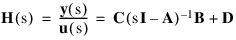
where:
■H(s) is the transfer function for the model
■I is the identity matrix of dimension equal to the number of system states
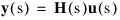
For a given vibration analysis, the system frequency response is given as:
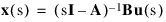
Modal Coordinates
Modal coordinates are states in the frequency domain solution associated with a specific mode. Modes most active in a frequency response can be identified from the modal coordinates. The modal coordinates are computed as:
Power Spectral Density (PSD)
PSD of output channels for given input PSDs is given as:
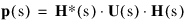
where:
■p(s) is the matrix of power spectral density
■H*(s) is the complex conjugate transpose of H(s)
■U(s) is the matrix of input spectral density
The matrix of input spectral densities is a diagonal matrix with the vibration actuator PSDs on the diagonal locations. Off-diagonal locations of this matrix are populated with cross-correlation PSD specification.
For example, for a model with two input channels with actuators of type PSD:
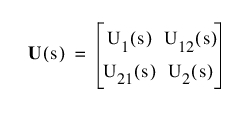
where:
■U1(s) is the PSD of input channel 1
■U2(s) is the PSD of input channel 2
■U12(s) is the cross correlation PSD of input channel 1 to input channel 2
■U21(s) is U12(s)
Transfer Function
Transfer function is a basic property of a model, and is computed as the magnitude and phase response at a given output channel for a given input channel with a unit swept sine vibration actuator.
For frequency response computation, the linearized model is represented as:
sx(s) = A x(s) + B u(s)
y(s) = C x(s) + D u(s)
where:
■s is the Laplace variable
■A, B, C and D are state matrices for the linearized model
The system transfer function can be represented as:

where:
■H(s) is the transfer function for the model
■I is the identity matrix of dimension equal to the number of system states
Creating a Multi-Run Script
You can create a simulation Script that you can use during multi-run simulations (such as Design study, Design of experiments (DOE), and so on).
To create a multi-run script:
1. Perform one of the following:
♦From the Vibration menu, point to Test, and then select Create Multi-Run Script.
♦From the Vibration menu, point to Test, and then select Vibration Analysis. In the Perform Vibration Analysis dialog box, select Create Multi-Run Script.
2. Complete the dialog box as described in Create Vibration Multi-Run Script.
3. Select OK.
Specifying Solver Settings
You can specify the default solver options for your simulation.
To specify the solver settings:
1. From the Vibration menu, point to Test, and then select Solver Settings.
2. Complete the dialog box as described in Solver Settings - Executable.
3. Select OK.