Modeling of Vibration Entities
This section presents the formulation for modeling the following vibration entities:
Vibration Input Channels
A vibration input channel defines the location, orientation, and type of forcing function to be applied. There are three types of input channels you can specify in Adams Vibration:
1. Force-type input channel applies a force at the specified marker. The expression for the force is as specified by the vibration actuator.
2. User-specified state variable applies the vibration actuator to a state variable that you may have created in your model. This input channel is useful in applying vibratory input to models that are represented by general dynamical elements, such as GSE/LSE/TFSISO.
3. Kinematic input channel applies displacement, velocity, or acceleration input. This form of the input channel imposes a kinematic constraint in the frequency domain at the specified marker. This constraint will result in removal of one degree of freedom at the marker at which it is applied.
Note: | Due to this constraint, the frequency response peaks may be shifted from the frequencies of the normal modes of the model. |
Vibration Actuators
A vibration actuator defines the magnitude and phase of the applied forcing function. Vibration actuators are required for modeling forcing function in forced response analysis. Phase angle, as defined in a vibration actuator, is with respect to the positive direction of the marker in the vibration input channel on which this actuator is defined.
Vibration actuators are applied at the input channel after the model is linearized. Therefore, vibration actuators are only in effect for frequency domain analysis and have no effect on the operation point analysis for the model.
Swept Sine Actuator
Force applied in a swept-sine actuator is defined as:
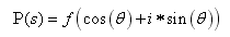
where:
■f = force magnitude
■θ = phase angle
The phase angle θ is measured with respect to positive direction of the marker axis for the input channel on which this actuator is acting.
Rotating Mass Actuator
Force Type
The force rotating mass actuator is represented by two actuators. The Leading and Lagging actuators are represented as:
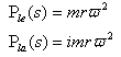
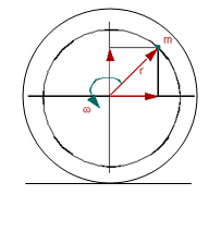
Figure 7 Rotating Mass Actuator
where:
■ = Force applied in leading actuator
= Force applied in leading actuator■ = Force applied in lagging actuator
= Force applied in lagging actuator■m = Unbalanced mass
■r = Radial offset
■ω = Frequency of excitation
When you want to incorporate vibratory effects due to an unbalanced mass in your vibration analysis, you must create two vibration actuators acting on the same input channel. The first actuator must be defined as a Leading actuator and the second as the Lagging actuator.
Moment Type
The moment type of rotating mass actuator is applicable for simulating moments due to radial, as well as axially offset unbalanced masses. The leading and lagging actuators are represented as:
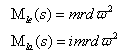
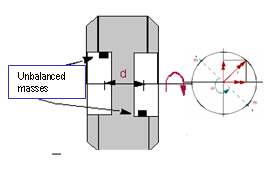
Figure 8 Rotating Mass Actuator - Moment Type
where:
■Mle = Moment applied in the leading actuator
■Mla = Moment applied in the lagging actuator
■d = Axial offset between unbalanced masses
As with the force type rotating mass actuator, to incorporate vibratory moment effects due to an unbalanced mass in your vibration analysis, you must create two vibration actuators acting on the same input channel. The first actuator must be defined as a Leading actuator and the second as the Lagging actuator.
PSD Actuator
The PSD actuator is for defining a spectrum that you want to apply to the model. For more information on power spectral density, see Reference 4. The PSD actuator is specified using a spline. You can create a spline using the Function Builder in Adams View. In Adams Vibration, you can specify the autocorrelation PSD of an input channel to itself, as well as the cross correlation PSD to other input channels. Section 4d provides details of how auto and cross correlations are used for computing PSD response.
PSD type actuators cannot be mixed with swept sine, rotating mass, or user-type actuators in the same vibration analysis. Response solution for PSD actuator is different from the force vibration response analysis.
Vibration Output Channels
Vibration output channels are defined using run-time expressions. These expressions can consist of kinematic or force expression or some combination of the state variables you define.
Frequency-dependent (FD) Modeling Elements
FD modeling elements are useful for incorporating compliant components with frequency-domain force characteristics in your model. These force characteristics may have been measured using a bench test in a laboratory. Several flavors of frequency-dependent modeling elements are available within Adams Vibration. From given force versus frequency characteristics, you can use system identification tools, such as described in article 1-KB12433 (see MSC Software Knowledge Base) for identifying parameters needed for defining FD element.
The FD modeling element is represented by a combination of spring and dampers in series and parallel. Each FD element adds two internal auxiliary states for each direction. These differential and output equations are contained within customized GSE subroutines in Adams Vibration.
A GFORCE element is used to apply forces on the I- and J-bodies between which you are applying the FD element. When you add a 3D FD element to your model, Adams Vibration automatically creates a GSE and GFORCE element in your model and instantiates the associated customized user subroutines for evaluation of the force in the FD element.
FD modeling elements are usable in frequency domain, as well as time domain analysis.
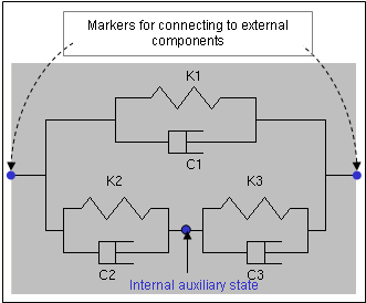
Figure 9 Scematic of One-dimentional FD Element