Create Section
In all cases the Section is normal to the node's X direction. The section dimensions correspond to the node's Y and Z directions as shown below. For details, see section Orientation of FE Part Nodes.
For the option: | Do the following: |
|---|---|
Cross Section | Select one of the following: ■Solid Rectangle ■Base - The width of the rectangle (dimension in node's z direction). ■Height - The height of the rectangle (dimension in node's y direction). 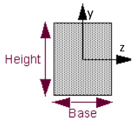 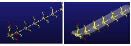 |
■Hollow Rectangle ■Base - The outer width of the rectangular shell (dimension in node's z direction). ■Height - The height of the outer rectangular shell (dimension in node's y direction). ■Thickness - Uniform width of the wall of the rectangular shell. 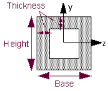 | |
■Solid Circle ■Radius - Radius of the circular cross-section. 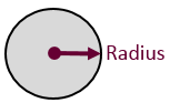 | |
■Hollow Circle ■Radius - Outer radius of the circular shell. ■Thickness - Width of the wall of the circular shell. 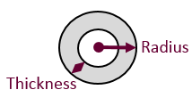 | |
■I-Beam ■Base - Enter the width of the I-beam (dimension in node's z direction). ■Height - Enter the height of I-beam (dimension in node's y direction). ■Flange - Enter the width of the flange of the I-beam. ■Web - Enter the width of the web of the beam. 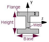 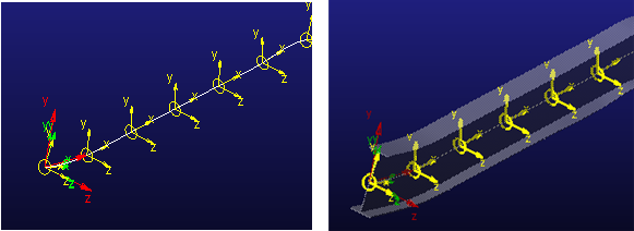 | |
■Properties ■Area - Specify the uniform area of the beam cross section. The centroidal axis must be orthogonal to this cross section. ■Iyz - Enter the product of inertia with respect to the y and z axes. ■Iyy, Izz - Enter the area moments of inertia about the neutral axes of the beam-cross sectional areas (y-y and z-z). These are sometimes referred to as the second moments of area about a given axis. They are expressed as unit length to the fourth power. ■Jxx - Enter the polar moment of inertia. It is the torsional constant which is used to assemble the torsional equation of motion describing the ability to resist torque. | |
■Ellipse ■Major axis (a): The longest diameter of an ellipse (dimension in node's z direction). ■Minor axis (b): The shortest diameter of an ellipse (dimension in node's y direction). 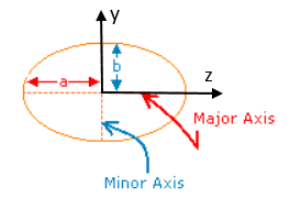 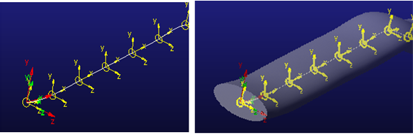 | |
■Generic ■Section's "Z" corresponds to Node's "Z". ■Section's "Y" corresponds to Node's "Y". 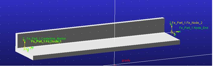 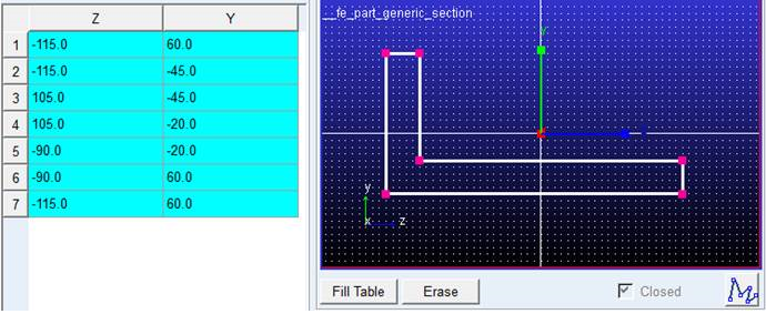 ■Fill Table: Click to fill the table with the created points. ■Erase: Click to clear the created points. ■Closed: Enforces that the section polyline close upon itself. This is the only option which the FE Part supports. |
Notes: | ■For FE Part results to be accurate, you need the centroid of the cross-section to lie on the FE Part centerline. Adams View does this automatically when using the standard section types for which it supports native-Adams geometry creation (solid elliptical/circular/rectangular and I-Bar). ■For a user-drawn cross-section, you must draw it such that its centroid ends up at X,Y=0,0 in the drawing box. ■For user-imported geometry, you must locate/orient it such that… ■one end is located co-incident with the node at S=0 (via ref mar) ■the centroid of the cross-section lies along the FE Part centerline ■the geometry is not longer than the FE Part centerline |