Orientation of FE Part Nodes
Node Orientation
■The trajectory of an FE Part is decided by either two markers or a reference GCURVE
■Based on the input an FE Part BSpline curve is created to align with reference GCURVE
■The BSpline is influenced by its reference marker, and all its point coordinates (XYZ) are with respect to the reference marker
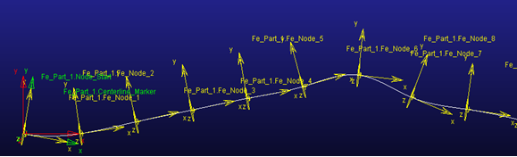
■Next, nodes are placed by Distance (S) along curve. The orientation of each node is based on the tangent to the BSpline curve at its location. This is shown by the yellow colored node icons in the image below
♦Node's X direction is always tangent to BSpline
♦Node's Y and Z direction are based on nature of BSpline curve. Thus, the node's orientation may vary based on nature of curve. It will gradually change along the path of curve in case of 3D spatial curve.
♦The node's Y and Z direction represent respective shear directions. Hence, the corresponding Section definition always aligns with these axes.
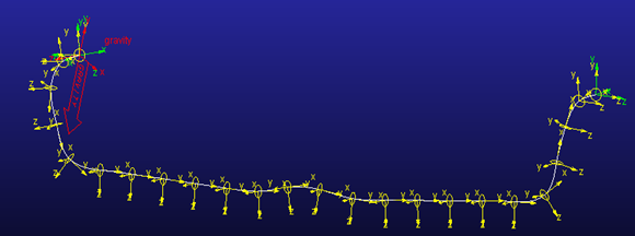
Example 3D Spatial Curve
If the BSpline is oriented spatially in 3D space, then its tangent (X), normal (Y) and bi-normal (Z) will be correctly oriented along the length of the BSpline:
And corresponding sections will follow the orientation of the respective nodes as shown below:
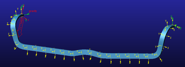
See the Create Section dialog box help for details on how the section is oriented relative to the node.