Create/Modify Filter Function
(Adams PostProcessor)
Plot → Filter → Create/Modify
Shortcut: Curve Edit toolbar → Filter Curve Tool → Right-click Filter Name text box → filter_function → Create
Plot → Filter → Create/Modify
Shortcut: Curve Edit toolbar → Filter Curve Tool → Right-click Filter Name text box → filter_function → Create
Creates or modifies a curve filter to eliminate noise on time signals or to emphasize a specific frequency content of a time signal. Adams PostProcessor supports two different types of filters:
■Butterworth filter - butter() in MATLAB™ developed by The MathWorks, Inc.
■Transfer function - A filter you define by directly specifying the coefficients of a transfer function.
Once you create a filter, you can apply it to any curve.
Learn about Filtering Curve Data.
For the option: | Do the following: |
|---|---|
Filter Name | If creating a filter function, enter a name for the filter. |
Defined by | Select to create either a Butterworth filter or a transfer function. |
If you selected Butterworth, Adams PostProcessor displays the following options: | |
Analog/Digital | Select to create either an analog or digital Butterworth filter. Learn About Filtering Methods. |
Filter Type | Select the type of filter: ■Low Pass - Removes frequencies above the cutoff frequency. ■High Pass - Removes frequencies below the cutoff frequency. ■Band Pass - Removes frequencies outside the two cutoff frequencies. ■Band Stop - Removes frequencies between the two cutoff frequencies. |
Order | Set how much the filter will have damped the signal at the cutoff frequency, often referred to as how sharp the filter is. ■First-order filter damps 3dB at the cutoff frequency. ■Second-order damps 6dB. ■Third-order damps 9dB. |
Cutoff Frequency (Scaled) - Digital filters Cutoff Frequency (Hz) - Analog filters | Set the frequency of cutoff. ■For a digital filter - Determines the cutoff frequency as a ratio of the Nyquist frequency (half the sample frequency). Therefore, for a signal sampled (simulated) with 100 Hz, the Nyquist frequency is 100/2=50Hz. A scaled cutoff frequency=0.3 then has a cutoff frequency=0.3*50=15 Hz. Note that if the same filter is applied to a signal sampled at 200 Hz, the filter cutoff is at 30 Hz. If you selected Band Pass or Band Stop for Filter Type, you must provide two cutoff frequencies. ■For an analog filter - Enter the cutoff frequency in the current units (rad/s or Hz). If you selected Band Pass or Band Stop for Filter Type, you must provide two cutoff frequencies. |
If you selected Transfer Function, Adams PostProcessor displays the following options: | |
Analog/Digital | Select to create either an analog or digital Butterworth filter. |
Create from Butterworth Filter | Select to display the Create Butterworth Filter dialog box to define the transfer function coefficients based on a Butterworth filter. |
Numerator/Denominator Coefficients | Specify the coefficients for the transfer function that define the filter. ■For an analog filter, the transfer function is defined by the continuous Laplace s polynomial. ■For a digital filter, the transfer function is defined in the z-plane. The coefficients should be given according to MATLAB convention, which is descending powers of s (or z): 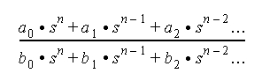 This differs from how a transfer function is defined for Adams Solver, where the coefficients are given in increasing order: 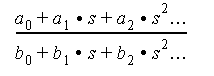 |
Check Format and Display Plot | Select to display a plot of the transfer function's gain (magnitude) or phase. Always check the filter before using it. Note: ■If you have not defined the filter correctly, an error message appears. ■If you’ve defined the filter correctly, a plot appears in which you can switch between the filter’s gain and phase plots and change scales. |