Link Tool
Ribbon menu Bodies tab Solids container → Link Tool 
or
Buid → Bodies/Geometry → Link Tool
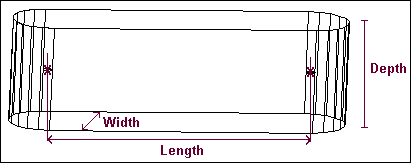
Creates a link by drawing a line indicating the link’s length. By default, the Link tool creates the link with a width that is 10% of the indicated length and a depth that is 5% of the length. The radius of the ends of the link is equal to half the width. Before drawing, you can also define the length, width, and depth of the link.
For the option: | Do the following: |
|---|---|
New Part/Add to Part/On Ground | Select either: ■New Part - Creates a new part. ■Add to Part - Adds the link to another part in your model. ■On Ground - Adds the link to ground. Note: Add geometry to ground if the geometry does not move or influence the simulation of your model. For example, if you are simulating a car driving around a race track, the geometry that defines the race track can be added to ground. |
Length | If desired, select and enter the length for the link. |
Width | If desired, select and enter the width for the link. |
Depth | If desired, select and enter the depth for the link. |
Note: | Two hotpoints appear after you draw the link: one hotpoint lets you modify the length of the link and the other hotpoint lets you modify the depth, width, and height. For more information on modifying geometry using hotpoints, see Using Hotpoints to Graphically Modify Geometry. |