Plate Tool
Ribbon menu → Bodies tab → Solids container → Plate Tool 
or
(Classic) Build → Bodies/Geometry → Plate Tool
Creates a plate, which is an extruded polygon solid with rounded corners. You create a plate by indicating the location of its corners. You must select at least three locations. The first location you select acts as an anchor point defining the position and orientation of the plate in space. The Plate tool creates markers at each location. The marker at the anchor point is called the reference marker.
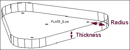
After you indicate the locations, the Plate tool creates a polygon with the specified number of sides and extrudes it. By default, it creates the plate with a depth that is 1 and has corners with radii of 1 in current length units. Before drawing, you can also specify the thickness and radius of the corners of the plate.
Note: | The reference marker of the plate determines the plate orientation and defines the plane of the plate to its x and y axes. Adams View defines the x and y axes of the reference marker using the working grid, if it is turned on, or the view screen. Adams View defines the plate vertices as the component of distance from the reference marker to the vertex marker as defined along the reference marker's y-axis. Therefore, if you choose a plate vertex marker that is out-of-plane from the xy plane of the reference marker, the vertex marker is not the actual plate vertex. |
For the option: | Do the following: |
|---|---|
New Part/Add to Part/On Ground | Select either: ■New Part - Creates a new part. ■Add to Part - Adds plate to another part in your model. ■On Ground - Adds the plate to ground. Tip: Add geometry to ground if the geometry does not move or influence the simulation of your model. For example, if you are simulating a car driving around a race track, the geometry that defines the race track can be added to ground. |
Thickness | Select and then enter the thickness of the plate. If you do not specify a thickness, Adams View creates the plate with a thickness of 1 in current length units. |
Radius | Select and then enter the radius of the plate corners. If you do not specify a radius, Adams View creates the plate with corners with radii of 1 in current length units. |
Note: | After you draw a plate, a hotpoint appears at the reference marker. It lets you change the depth of the plate. For more information on modifying geometry using hotpoints, see Using Hotpoints to Graphically Modify Geometry You can also use the Geometry Modify Shape Plate dialog box to change the markers used to define the plate, the thickness of the plate, and the radius of the corners of the plate. |