Tools and Techniques
There are several techniques in Adams View that can help you create objects with precision and speed.
Turning Selection Highlighting On and Off
Adams View provides a Dynamic Model Navigator that highlights entire objects or edges, faces, and points on those objects so you can easily select, place, or align an object that you are creating or a rotate a view.
The Model Navigator highlights objects and displays their names as you move the cursor over them within the main window. For example, when you create a marker, the Model Navigator highlights edges, faces, and points you might want to use to orient the axes of the coordinate system. In addition, if you are adding a point or joint to a part, the Model Navigator highlights the different parts in your model to which you can add the point or joint. The figure below shows the Model Navigator highlighting line geometry.
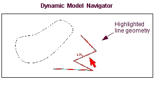
The Model Navigator only highlights those objects that are appropriate for the operation you are currently performing. For example, when you are aligning the faces of two parts, the Model Navigator only highlights faces. It does not highlight edges or points. In addition, if you are chaining together wire geometry, the Model Navigator only highlights wire geometry.
Finally, when you are defining a direction, the Model Navigator lets you select points, edges, or faces. When you select an edge or face, the Model Navigator then lets you select the direction along the object that you want to define since edges and faces don't provide unique direction.
To improve performance you can turn off the Model Navigator.
To turn off the Dynamic Model Navigator:
■During a selection operation, press the Ctrl key.
Setting Snapping to Objects
As you build your model through the graphical interface, Adams View automatically snaps the object that you are creating to surrounding geometric objects. This can help you quickly align parts or draw objects that touch other objects.
To turn off object snapping:
■As you create an object, press the Ctrl key.
Note: | If the Working grid is on, when you draw, move, resize, or reshape geometry, the geometry automatically snaps to the grid points. Learn about turning on and off the working grid. |
Entering Precise Location Coordinates
As you create an object, such as a design point or a force, Adams View often asks you to select the position of the object. You can do this graphically by clicking the mouse button when the cursor is in the screen or you can enter location coordinates to precisely set its location. You can enter the location relative to the origin of the working grid, the global coordinate system, or any other object on the screen.
To enter location coordinates:
1. When Adams View asks you for a location, right-click.
The LocationEvent dialog box appears as shown below. The current coordinates of the cursor appear in the upper box.
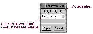
2. In the upper box, enter the coordinates at which to place the object.
3. Select the element (Working grid, global coordinate system, or modeling object) to which the coordinates are relative. By default, the coordinates are relative to the working grid.
4. In the lower box, enter the object to which the coordinates are relative. You only need to enter an object if you selected that the coordinates are relative to an object.
Tips on Entering Object Names in Text Boxes.
5. Select Apply.
Selecting from a List of Objects
When you perform a modeling operation, such as set an object's appearance or specify a force direction, and you need to select an object from the screen, you can display a list of all objects in the area surrounding the cursor and then select the desired object from the list. Note that this only works during a modeling operation. The objects include geometric objects, such as object faces, vertices, and more.
To display a list of all objects in an area of the screen:
1. Right-click the area of the screen containing the desired object.
A selection box of all the objects in the area appears.
2. As you highlight the desired object in the list, Adams View also highlights the object on the screen.