Creating Trace Spline
Traces follow the motion of a point or part (circle or cylinder) as it moves relative to a second part.
You can create two- or three-dimensional splines from traces. A trace that follows a point creates a three-dimensional spline. The point can move in any direction relative to the part on which the trace was created.
A trace that follows a circle or cylinder creates a two-dimensional spline. Adams View creates the curve in the xy plane of the base marker (the marker on the part on which the trace was created). Adams View assumes the circle is parallel to the plane or the cylinder is perpendicular to the plane, and that the motion is in this plane.
When you create the trace, Adams View creates a base marker that is oriented properly with respect to the circle or cylinder you selected. Therefore, the curve will be in the plane of the circle in its initial position. You have to make sure that the motion is in the plane of the circle or you will get unexpected results. Therefore, be sure to think of the circle trace as occurring in the plane of the circle. It can be any plane, not necessarily the global xy plane.
Example of Creating Spline Geometry
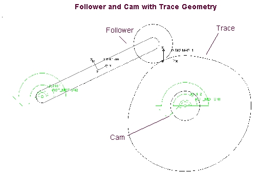
For example, if you want to create a surface on a cam that makes a follower part move in a particular way relative to each other, you can create the necessary surface geometry by following the movement of the two parts with a trace that Adams View turns into spline geometry.
You start creating the spline geometry by first making the follower and cam move the way you want them to relative to each other. You place a motion on the cam joint that rotates the cam once per second. Next, you place a motion on the follower joint that moves it up and down once each second.
After simulating the motion, you then request Adams View to trace the motion of the follower circle relative to the cam circle and create spline geometry based on that geometry. The following figure shows the cam and follower geometry and the trace that Adams View creates.
To create a spline from a trace:
1. Set up your model so that it creates the desired motion after which you want the spline to be modeled.
2. Run a simulation of your model as explained in Performing an Interactive Simulation.
3. Reset the simulation by selecting the Simulation Reset tool  from either the Simulation container on the Main toolbox or the Simulation palette. See Interactive Simulation Palette and Container dialog box help.
from either the Simulation container on the Main toolbox or the Simulation palette. See Interactive Simulation Palette and Container dialog box help. 4. Select the Results tab. In Review section, select Create Trace Spline icon.
icon.
icon.From the Review menu, select Create Trace Spline (Classic).
5. Select a point, marker, circle, or cylinder with which to trace, and then select the part on which to trace.
6. You can trace on ground or any other part. For a point trace, select anywhere on the point or part. For a circle or cylinder, however, be careful where you select because where you select on the circle and the part determines the resulting trace geometry. There are usually two possible traces, one on each side of the circle or cylinder.
7. Replay the simulation to see the selected object follow the trace curve.
Tip: | The following are some tips on creating splines from traces: ■When you trace an object, the point/circle should move in a smooth, even path or the trace ends up looking like scribbles on the screen. ■If the path is closed, you should simulate for one cycle only. ■If the trace is uneven or complex, you can get a strange looking curve as a result. As an alternative to the Create Trace Spline menu command, you can use the Command Navigator to execute the command: geometry create curve point_trace. It lets you create a polyline instead of a spline, which works better if the trace is uneven or complex. In that case, the motion of the cam or slot is transferred through the traced curve and gives the desired follower motion. |