Example of Using the Adams View Controls Toolkit
Overview
The following example illustrates how you can use the Adams View Controls Toolkit to control the speed of a part in your model based on a known speed profile. To download the model for this example (ControlVelocity.cmd), go to the following simcompanion link:
To see other examples of the Adams View Controls Toolkit, see the following articles in the simcompanion website.
Example of: | In the KBA: |
|---|---|
General use of Adams View Controls Toolkit | |
Feedback control system without using controls package elements | |
Proportional feedback control |
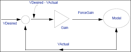
Figure 1 Control Block Diagram
All of the connecting lines in the diagram are elements that you can create using the Adams View Controls Toolkit. The specified speed profile is entered into a spline element named SpeedSpline. You can create this using Build → Data Elements → Spline → New, and then entering the speed vs. time profile that you want. (Alternatively, you could select File → Import Test Data to enter your values.)
The lines in Figure 1 correspond to the following toolkit elements
VActual | ■Block Type: Input Function (input-signal block) ■Function: VX(.ControlVelocity.PART_2.cm). This is the measured velocity of the ball with respect to ground. |
VDesired | ■Block Type: Input Function (input-signal block) ■Function: AKISPL(time,0,.ControlVelocity.SpeedSpline, 0). This is a look-up in the defined spline element SpeedSpline. |
VDifference | ■Block Type: Summing Junction ■Input1: VDesired (+) ■Input2: VActual (-) |
ForceGain | ■Block Type: Gain ■Input: VDifference ■Gain: 100 |
After you run the model for one second and 100 time steps, you see two strip charts:
■The actual ball speed measure
■The desired speed versus time profile (using the defined spline element SpeedSpline)
They should look very similar when the simulation is run.