Examples of Customizing the Adams View Interface
Overview
The following examples illustrate basic tasks you can perform with the Menu and Dialog-Box Builders:
Modifying a Standard Menu
In this example, you’ll add a button to an existing menu.
To modify a standard menu:
1. On the Tools menu, point to Menu, and then select Modify.
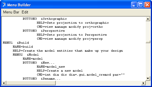
The Menu Builder appears.
2. Scroll down to the Build menu section.
3. Add a button called Verify (see syntax below).
4. In the Menu Builder, on the Menu Bar menu, select Apply.
The Build menu now contains a button called Verify. To test it, create a model and then select the Verify button. An information dialog box appears, and tells you whether or not your model verified successfully.
Modifying a Standard Dialog Box
In this example, you delete a tool from the Main toolbox. It shows you how easy it is to edit existing dialog boxes.
To delete a tool:
1. On the Tools menu, point to Dialog Box, and then select Modify.
The Database Navigator appears.
2. Double-click moag.
The Dialog-Box Builder appears.
3. Double-click the Main toolbox tool that you want to delete. For example, double-click the Select tool.
4. In the Dialog-Box Builder, on the Edit menu, select Delete.
Adams View removes the selected tool from the Main toolbox.
Creating and Modifying a Custom Dialog Box
In this example, you create a custom dialog box that you’ll modify to include buttons that let you set the material type of a selected part in Adams View. You’ll then create a custom menu to display the dialog box.
Creating a Custom Dialog Box
To create a custom dialog box:
1. On the Tools menu, point to Dialog Box, and then select Create.
2. On the Dialog Box menu, select New.
3. Assign a name to your dialog box. In this case, use Materials.
4. Select the OK, Apply, and Close predefined buttons.
5. Select OK to display your dialog box.
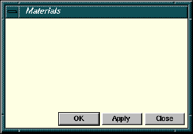
Figure 10 Example Dialog Box with Predefined Buttons
Modifying Your Dialog Box
Now you can modify the dialog box you’ve created to create a field for selecting a part and create a material type button.
To modify the dialog box:
1. Once you’ve created your dialog box, double-click its background to modify it.
2. Use the Dialog-Box Builder to create a label and name it Part.
3. Create a field next to the Part label. You will use the field to indicate the part for which you want to change the material type. In the next steps, you set up the field to accept parts.
4. Double-click the field and in the Dialog Box Builder set Attributes to Value.
5. Set Object Type to Any.
6. In Type Filter, enter Part.
7. Select Apply.
8. Align the two fields using the tools on the Dialog-Box Builder toolbar.
9. Create another label and name it Material.
10. Create one button and align it next to the Material label.
11. Label the button Aluminum.
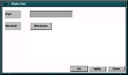
Figure 11 Example Dialog Box with One Field and One Button
Writing Commands for Your Dialog Box Objects
In this section, you’ll create commands for the button you created in the last example, and you’ll also create buttons for all material types in Adams View. You can use the Command Navigator, the command window, or the log file to find the commands you need.
To see the default material types Adams View supplies, do the following in the Command Navigator:
1. Double-click +material, and then double-click modify.
A dialog box appears.
2. Right-click the Material Name box, point to Material, and select Browse.
The Database Navigator lists all the default material types.
To create the buttons and add commands:
1. Double-click the Aluminum button and write the command corresponding to its material type. Make sure your command indicates the field you want to associate with the Aluminum button. The next figure shows the commands that you’d enter.
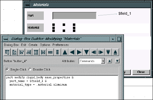
Figure 12 Example of Entering Commands for Aluminum Button
2. Copy the Aluminum button.
3. Paste it next to the existing Aluminum button, and change its name to Brass.
4. Repeat steps 2 and 3 until your dialog box resembles the one shown next.
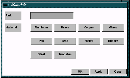
Figure 13 Example Dialog Box Containing all Material-Type Buttons
5. Copy the command used for the Aluminum button and modify it for the other buttons.
6. From the Options menu, select Test Box to activate the new dialog box for testing.
7. Use the right mouse button to click in the field next to the Part label in your dialog box, and select the part to which you want to apply a certain material type.
8. Click the desired Material button.
Your part now has the assigned material type.
9. Click OK to close the dialog box.
Creating a Custom Menu on the Menu Bar
Now, you’ll create a custom menu to display the dialog box you created and modified in the previous steps.
To create a custom menu:
1. On the Tools menu, point to the Menu, and then select Modify.
2. Enter the syntax necessary to create a new menu, following the format in the Menu Builder. Name your menu Custom.
3. Under the new menu, create two buttons: Menu Builder and Custom Dialog Box.
4. Write the commands for the two buttons such that Menu Builder displays the Menu Builder and Custom Dialog Box displays your Materials dialog box.
Using Command Files to Customize the Interface
We’ve provided eight command files containing macros and interface changes as an example of using Adams View command (.cmd) files to customize your interface.
The example consists of a build command file, build_my_gui.cmd, that you import into Adams View. The build file imports the seven other command files, four of which contain the macros and three of which contain the custom dialog boxes to run the three macros. The dialog boxes have fields for entering data that is passed to the parameters of the macros. The build_my_gui.cmd file also creates the custom menus that are used to execute the macros.
When you import the build command file into Adams View, it creates a new set of menus in the main menu bar (at the top of the Adams View window). The top menu is called Marker. Under this are:
Toggle all visibility
Toggle some visibility
Scale Up
Scale Down
The .cmd files for this example are listed in Command Files. You can also find the files in the Adams simcompanion website (http://simcompanion.mscsoftware.com/). If you do not have access to the simcompanion, you can use the text copy file tool in Adobe Acrobat Reader to copy the text in Command Files to files and save the files with a .cmd extension. The text copy tool is available in most browsers when you are viewing a pdf.
Importing and Running this Example
To run this example:
1. Download all the .cmd files to the same directory on your computer and start Adams View from that directory. If you do not start Adams View from this directory, you will received errors.
2. Use the File −> Import (or the file command read commands) to import the file build_my_gui.cmd.
3. Experiment with each menu to see what it does to the markers in your sample model. Then, edit the various .cmd files to better understand how everything works.
What This Example Illustrates
We recommend the following when creating macros as command files as this example illustrates:
1. Create all your macros, test them to make sure they work correctly, and then save them as .cmd files. If you use the Macro Builder to create your macros, export each to a .cmd file when you are finished. Once you get familiar with the Adams View commands necessary to create macros, you may find it faster and easier to create your associated .cmd files using a text editor.
2. Create all your custom dialog boxes that are required to execute the macros, test them to make sure they work correctly, and then save them as .cmd files. If you create your dialog boxes in Adams View (by either using the Dialog Box Builder or double-clicking on the name of the macro from within the Command Navigator), then you should export each to a .cmd file when you are finished. As with macros, once you get familiar with the Adams View commands necessary to create custom dialog boxes, you may find it faster and easier to create your associated .cmd files using a text editor.
3. Create a build .cmd file that contains the commands required to accomplish three main objectives:
■Import each of your macro .cmd files into Adams View.
■Import each of your custom dialog box .cmd files into Adams View.
■Create each of the custom menus in Adams View needed to execute the macros, either directly or indirectly (by displaying the custom dialog boxes).
Command Files
Table 1 lists and briefly explains the command files that make up this example. The text of the command files follows the table.
The file: | Does the following: |
|---|---|
build_my_gui.cmd | Reads in the other command files (file command read file_name = ...) Creates the macros contained in the four mac_ command files (macro create macro_name = ...) Customizes the interface (interface menu create menu_name = ...) |
dbox_sca_down.cmd | Creates a dialog box for reducing the size of markers. |
dbx_sca_up.cmd | Creates a dialog box for increasing the size of markers. |
dbx_vis_some.cmd | Creates a dialog box to set the visibility of selected markers. |
mac_sca_down.cmd | Contains a macro that reduces the size of selected markers. |
mac_sca_up.cmd | Contains a macro that increases the size of selected markers. |
mac_vis_all.cmd | Contains a macro that turns on the visibility of selected markers. |
build_my_gui.cmd
Customizes the interface and imports macros.
! --- Import macros
!
!
macro read &
macro_name = mac_vis_all &
file_name = "mac_vis_all.cmd" &
user_entered_command = "marker visibility all"
!
macro read &
macro_name = mac_vis_some &
file_name = "mac_vis_some.cmd" &
user_entered_command = "marker visibility some"
!
macro read &
macro_name = mac_scale_up &
file_name = "mac_scale_up.cmd" &
user_entered_command = "marker scale up"
!
macro read &
macro_name = mac_scale_down &
file_name = "mac_scale_down.cmd" &
user_entered_command = "marker scale down"
! --- Import dialog boxes (to execute those macros having parameters)
!
file command read file = "dbox_vis_some.cmd"
file command read file = "dbox_sca_up.cmd"
file command read file = "dbox_sca_down.cmd"
! --- Create custom menus
!
interface menu create &
menu_name = .gui.main.mbar.markers &
label = "&Markers"
!
interface push_button create &
push_button_name = .gui.main.mbar.markers.b_vis_all &
label = "&Toggle all visibility" &
commands = "int com com=\"marker vis all\""
!
interface push_button create &
push_button_name = .gui.main.mbar.markers.b_vis_some &
label = "&Toggle some visibility..." &
commands = "interface dialog_box display dialog_box_name = .gui.mar_vis_som"
!
interface push_button create &
push_button_name = .gui.main.mbar.markers.b_scale_up &
label = "Scale &Up..." &
commands = "interface dialog_box display dialog_box_name =.gui.mar_sca_up"
!
interface push_button create &
push_button_name = .gui.main.mbar.markers.b_scale_dn &
label = "Scale &Down..." &
commands = "interface dialog_box display dialog_box_name =.gui.mar_sca_dow"
dbox_sca_down.cmd
Creates a dialog box for scaling markers.
!
interface dialog_box create &
dialog_box_name = .gui.mar_sca_dow &
help_text = "Marker Scale Down" &
location = 410.0, 120.0 &
height = 68.0 &
width = 404.0 &
units = pixel &
horiz_resizing = attach_left &
vert_resizing = attach_top &
title = "Marker Scale Down" &
iconifiable = no &
execution_commands = "marker scale down &", " ‘markers = $f_markers‘" &
decorate = yes &
resizable = yes &
grab_all_input = no
!
interface label create &
label_name = .gui.mar_sca_dow.l_markers &
location = 2.0, 2.0 &
height = 25.0 &
width = 160.0 &
units = pixel &
horiz_resizing = attach_left &
vert_resizing = attach_top &
justified = left &
text = "Markers"
!
interface field create &
field_name = .gui.mar_sca_dow.f_markers &
location = 162.0, 2.0 &
height = 25.0 &
width = 240.0 &
units = pixel &
horiz_resizing = expand &
vert_resizing = attach_top &
scrollable = no &
editable = yes &
required = yes &
execute_cmds_on_exit = no &
number_of_values = 0 &
object_type = old &
type_filter = marker
!
interface push_button create &
push_button_name = .gui.mar_sca_dow.OK &
location = 138.0, 35.0 &
height = 25.0 &
width = 76.0 &
units = pixel &
horiz_resizing = attach_right &
vert_resizing = attach_bottom &
label = "OK" &
commands = "interface dialog execute dialog=$_parent undisplay=yes" &
default = true
!
interface push_button create &
push_button_name = .gui.mar_sca_dow.Apply &
location = 228.0, 35.0 &
height = 25.0 &
width = 76.0 &
units = pixel &
horiz_resizing = attach_right &
vert_resizing = attach_bottom &
label = "Apply" &
commands = "interface dialog execute dialog=$_parent undisplay=no"
!
interface push_button create &
push_button_name = .gui.mar_sca_dow.Cancel &
location = 318.0, 35.0 &
height = 25.0 &
width = 76.0 &
units = pixel &
horiz_resizing = attach_right &
vert_resizing = attach_bottom &
label = "Cancel" &
commands = "interface dialog undisplay dialog=$_parent"
dbx_sca_up.cmd
Creates a dialog box for increasing the size of markers.
!
interface dialog_box create &
dialog_box_name = .gui.mar_sca_up &
help_text = "Marker Scale Up" &
location = 410.0, 120.0 &
height = 68.0 &
width = 404.0 &
units = pixel &
horiz_resizing = attach_left &
vert_resizing = attach_top &
title = "Marker Scale Up" &
iconifiable = no &
execution_commands = "marker scale up &", " ‘markers = $f_markers‘" &
decorate = yes &
resizable = yes &
grab_all_input = no
!
interface label create &
label_name = .gui.mar_sca_up.l_markers &
location = 2.0, 2.0 &
height = 25.0 &
width = 160.0 &
units = pixel &
horiz_resizing = attach_left &
vert_resizing = attach_top &
justified = left &
text = "Markers"
!
interface field create &
field_name = .gui.mar_sca_up.f_markers &
location = 162.0, 2.0 &
height = 25.0 &
width = 240.0 &
units = pixel &
horiz_resizing = expand &
vert_resizing = attach_top &
scrollable = no &
editable = yes &
required = yes &
execute_cmds_on_exit = no &
number_of_values = 0 &
object_type = old &
type_filter = marker
!
interface push_button create &
push_button_name = .gui.mar_sca_up.OK &
location = 138.0, 35.0 &
height = 25.0 &
width = 76.0 &
units = pixel &
horiz_resizing = attach_right &
vert_resizing = attach_bottom &
label = "OK" &
commands = "interface dialog execute dialog=$_parent undisplay=yes" &
default = true
!
interface push_button create &
push_button_name = .gui.mar_sca_up.Apply &
location = 228.0, 35.0 &
height = 25.0 &
width = 76.0 &
units = pixel &
horiz_resizing = attach_right &
vert_resizing = attach_bottom &
label = "Apply" &
commands = "interface dialog execute dialog=$_parent undisplay=no"
!
interface push_button create &
push_button_name = .gui.mar_sca_up.Cancel &
location = 318.0, 35.0 &
height = 25.0 &
width = 76.0 &
units = pixel &
horiz_resizing = attach_right &
vert_resizing = attach_bottom &
label = "Cancel" &
commands = "interface dialog undisplay dialog=$_parent"
dbx_vis_some.cmd
Sets the visibility of selected markers.
!
interface dialog_box create &
dialog_box_name = .gui.mar_vis_som &
help_text = "Marker Visibility Some" &
location = 184.0, 108.0 &
height = 118.0 &
width = 425.0 &
units = pixel &
horiz_resizing = attach_left &
vert_resizing = attach_top &
title = "Marker Visibility Some" &
iconifiable = no &
execution_commands = "marker visibility some &", &
" ‘markers = $f_markers‘" &
decorate = yes &
resizable = yes &
grab_all_input = no
!
interface label create &
label_name = .gui.mar_vis_som.l_markers &
location = 2.0, 2.0 &
height = 25.0 &
width = 160.0 &
units = pixel &
horiz_resizing = attach_left &
vert_resizing = attach_top &
justified = left &
text = "Markers"
!
interface field create &
field_name = .gui.mar_vis_som.f_markers &
location = 162.0, 2.0 &
height = 25.0 &
width = 261.0 &
units = pixel &
horiz_resizing = expand &
vert_resizing = attach_top &
scrollable = no &
editable = yes &
required = yes &
execute_cmds_on_exit = no &
number_of_values = 0 &
object_type = old &
type_filter = marker
!
interface push_button create &
push_button_name = .gui.mar_vis_som.OK &
location = 159.0, 85.0 &
height = 25.0 &
width = 76.0 &
units = pixel &
horiz_resizing = attach_right &
vert_resizing = attach_bottom &
label = "OK" &
commands = "interface dialog execute dialog=$_parent undisplay=yes" &
default = true
!
interface push_button create &
push_button_name = .gui.mar_vis_som.Apply &
location = 249.0, 85.0 &
height = 25.0 &
width = 76.0 &
units = pixel &
horiz_resizing = attach_right &
vert_resizing = attach_bottom &
label = "Apply" &
commands = "interface dialog execute dialog=$_parent undisplay=no"
!
interface push_button create &
push_button_name = .gui.mar_vis_som.Cancel &
location = 339.0, 85.0 &
height = 25.0 &
width = 76.0 &
units = pixel &
horiz_resizing = attach_right &
vert_resizing = attach_bottom &
label = "Cancel" &
commands = "interface dialog undisplay dialog=$_parent"
!
interface separator create &
separator_name = .gui.mar_vis_som.sep_1 &
location = 4.0, 44.0 &
height = 3.0 &
width = 417.0 &
units = pixel &
horiz_resizing = attach_left &
vert_resizing = attach_top
mac_sca_down.cmd
Creates a macro that scales selected markers.
!USER_ENTERED_COMMAND marker scale down
!WRAP_IN_UNDO NO
!$MARKERS:t=marker:c=0
marker attributes scale=0.5 marker_name=$MARKERS
mac_sca_up.cmd
Creates a macro that increases the size of selected markers.
!USER_ENTERED_COMMAND marker scale up
!WRAP_IN_UNDO NO
! $MARKERS:t=marker:c=0
marker attributes scale_of_icons=2.0 marker_name=$MARKERS
mac_vis_all.cmd
Creates a macro that turns on the visibility of all markers.
!USER_ENTERED_COMMAND marker visibility all_on_off
!WRAP_IN_UNDO NO
marker attributes visibility=toggle marker_name=.*
mac_vis_some.cmd
Creates a macro that turns on the visibility of selected markers.
!USER_ENTERED_COMMAND marker visibility some_on_off
!WRAP_IN_UNDO NO
! $MARKERS:t=marker:c=0
marker attributes visibility=toggle marker_name=$MARKERS