force create element_like beam
Allows you to create a beam object.
Example:
force create element_like beam & | |
|---|---|
beam_name = | BEAM_1 & |
adams_id = | 2 & |
Comments = | “” & |
Ixx = | 2.11 & |
Iyy = | 1.8 & |
Izz = | 1.9 & |
Length = | 10 |
Description:
Parameter | Value Type | Description |
|---|---|---|
beam_name | String | Specifies the name of the new beam. You may use this name later to refer to this beam. View will not allow you to have two beams with the same name, so you must provide a unique name. |
adams_id | Integer | Specifies an integer used to identify this element in the Adams data file. |
Comments | String | Specifies comments for the object being created or modified. |
Ixx | Real number greater than 0 | Specifies the polar area moment of inertia about the X axis of a cross section perpendicular to the length of the beam. |
Iyy | Real number greater than 0 | Specifies the principal area moment of inertia about the Y axis of a cross section perpendicular to the length of the beam. |
Izz | Real number greater than 0 | Specifies the principal area moment of inertia about the z axis of a cross section perpendicular to the length of the beam. |
y_shear_area_ratio | Real number greater than 0 | Specifies the shear area ratio in the y direction. This is the correction factor for shear deflection in the y direction for Timeshenko beams. |
z_shear_area_ratio | Real number greater than 0 | Specifies the shear area ratio in the y direction. This is the correction factor for shear deflection in the z direction for Timeshenko beams. |
Youngs_modulus | Real number greater than 0 | Specifies Young's modulus of elasticity for the beam material. |
Shear_modulus | Real number greater than 0 | Specifies the shear modulus of elasticity for the beam material. |
length | Real number greater than 0 | Specifies the undeformed length of the beam along the x axis of the J marker. |
area_of_cross_section | Real number greater than 0 | Specifies the uniform area of the beam cross section. |
Damping ratio | Real number greater than 0 | Specifies a ratio for calculating the structural damping matrix for the beam. Adams multiplies the stiffness matrix by the value of DAMPING_RATIO to obtain the damping matrix. |
matrix_of_damping_terms | Specifies a six-by-six structural damping matrix for the beam. | |
location | Specifies the locations to be used to define the position of a force during its creation. | |
Orientation | Specifies the orientation of the J marker for the force being created using three rotation angles. | |
Along_axis_orientation | Specifies the orientation of a coordinate system (e.g. marker or part) by directing one of the axes. Adams View will assign an arbitrary rotation about the axis. | |
in_plane_orientation | Specifies the orientation of a coordinate system (e.g. marker or part) by directing one of the axes and locating one of the coordinate planes. | |
i_part_name (Required) | Specifies the part that is the first of the two parts that this force acts between. | |
j_part_name (Required) | Specifies the part that is the second of the two parts that this force acts between. Adams View applies the force on one part at the J marker and the other at the I marker. These markers are automatically generated using this method of force creation. | |
i_marker_name (Required) | Specifies a marker on the first of two parts connected by this force element. Adams View connects this element to one part at the I marker and to the other at the J marker. | |
j_marker_name | Specifies a marker on the second of two parts connected by this force element. Adams View connects this element to one part at the I marker and to the other at the J marker. | |
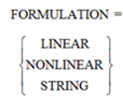 | Specifies the theory to be used to define the force this element will apply. By default the LINEAR theory is used. If the NONLINEAR option is used, the full non linear Euler-Bernoulli theory is used. If the STRING option is used, a simplified non linear theory is used. The simplified non linear theory may speed up your simulations with little performance penalties. |
Extended Definition:
1. The beam, which is massless and has a uniform cross section, is modeled as a linear translational and a linear rotational action-reaction force between two markers. The forces the beam produces are linearly dependent on the relative displacements and the relative velocities of the markers at its endpoints. The x-axis of the J marker defines the centroidal axis of the beam. The y-axis and the z-axis of the J marker are the principal axes of the cross section. They are perpendicular to the x-axis and to each other. When the beam is in an undeflected position, the I marker has the same angular orientation as the J marker, and the I marker lies on the x-axis of the J marker. The following constitutive equations define how Adams uses the data you input for a beam to apply a force and a torque to the I marker depending on the displacement and velocity of the I marker relative to the J marker. Adams applies a force of equal magnitude and opposite direction to the J marker.
[Fx] [K11 0 0 0 0 0 ] [x]
[Fy] [0 K22 0 0 0 K26] [y]
[Fz] = - [0 0 K33 0 K35 0 ] [z]
[Tx] [0 0 0 K44 0 0 ] [a]
[Ty] [0 0 K35 0 K55 0 ] [b]
[Tz] [0 K26 0 0 0 K66] [c]
[C11 C21 C31 C41 C51 C61] [Vx]
[C21 C22 C32 C42 C52 C62] [Vy]
-[C31 C32 C33 C43 C53 C63] [Vz]
[C41 C42 C43 C44 C54 C64] [Wx]
[C51 C52 C53 C54 C55 C65] [Wy]
[C61 C62 C63 C64 C65 C66] [Wz]
Note that both matrices, Cij and Kij, are symmetric, i.e. Cij=Cji and Kij=Kji. You define the twenty-one unique damping coefficients when you write the BEAM statement. Adams defines the Kij's in the following way:
K11 = E A / L
K22 = 12 E Izz /[L**3 (1+Py)]
K26 = -6 E Izz /[L**2 (1+Py)]
K33 = 12 E Iyy /[L**3 (1+Pz)]
K35 = 6 E Iyy /[L**2 (1+Pz)]
K44 = G Ixx / L
K55 = (4+Pz) E Iyy /[L (1+Pz)]
K66 = (4+Py) E Izz /[L (1+Py)]
where Py = 12 E Izz ASY/(G A L**2) and Pz = 12 E Iyy ASZ/(G A L**2)
2. The BEAM statement implements a force in the same way the FIELD statement does, but the BEAM statement requires you to input only the values of the beam's physical properties, which Adams uses to calculate the matrix entries. For a force request, the forces returned are the forces the J marker exerts upon the I marker.
3. The constitutive equations shown above define the forces and moments exerted on the I marker. These forces and moments are due to relative displacements and velocities of the I marker with respect to the J marker. Because of force transfer, the reaction moments at the J marker are usually not the same as the applied moments at the I marker.
4. Normally, entity names are composed of alphabetic, numeric, or '_' (underscore) characters, and start with an alphabetic or '_' character. They may be of any length. For more information, see Using Extended Names. By enclosing the name in double quotes, you may use other printable characters, or start the name with a numeral. If a name contains characters, or starts with a numeral, you must always quote the name when entering it. Note that you can specify the parentage of an entity (e.g. what part "owns" a marker or a geometry element) when you CREATE it by changing the name. If you enter just the entity name, then the default parent will be assigned by Adams View. If you type in the full name, then you may override the default parent. In most cases, when creating an entity, Adams View will provide a default name. The default name that Adams View provides will specify the parentage that it has assumed. You may, of course, delete this name and use your own. The form of a full name is: "...._NAME.GRAND_PARENT_NAME.PARENT_NAME.ENTITY_NAME"
The number of levels used varies from case to case and the parentage must exist before an entity can be assigned to it.
5. When you use the FILE ADAMS_DATA_SET WRITE command, Adams View writes an Adams data file for your model. Adams requires that each modeling element be identified by a unique integer identifier. If you use this parameter to specify a non-zero identifier, Adams View will use it in the corresponding statement in the Adams data file. You may also enter zero as an identifier, either explicitly or by default. The next time you write an Adams file, Adams View will replace the zero with a unique, internally generated identifier. Adams View will permanently store this identifier with the element just as if you had entered it yourself. Normally, you would let all identifiers default to zero, and Adams View would generate the identifiers for you. You are never required to enter a non-zero identifier. You only need to specify it if, for some reason, you wish to control the Adams file output.
6. By definition, the beam lies along the positive X axis of the J marker. You should compute IXX about the X axis of the J marker. Values for the Ixx parameter are:A REAL NUMBER GREATER THAN 0
7. By definition, the beam lies along the positive X axis of the J marker. You should compute IYY about the Y axis of the J marker.
8. By definition, the beam lies along the positive X axis of the J marker. You should compute IZZ about the Z axis of the J marker.
9. The y_shear_ratio is the area of the beam cross section divided by the area of the beam cross section that resists y-direction shear forces. If you want to neglect the deflection due to y-direction shear, set the ratio to zero.
10. The z_shear_ratio specifies the shear area ratio in the z direction. This is the correction factor for shear deflection in the z direction for Timeshenko beams.
11. Because the ‘matrix_of_damping _terms’ matrix is symmetric, you need to specify only one-half of it. The following matrix shows the values to input:
[r01 ] [r02 r07 ] [r03 r08 r12 ]
[r04 r09 r13 r16 ] [r05 r10 r14 r17 r19 ] [r06 r11 r15
r18 r20 r21]
Enter the elements by columns from top to bottom, then from left to right. If you do not use either CMATRIX or CRATIO, CMATRIX defaults to a matrix with thirty-six zero entries; i.e. r1 through r21, each default to zero.
12. The I and J markers will be automatically created at the location specified by the ‘location’ parameter on the I_PART_NAME and J_PART_NAME respectively. By default, you supply Cartesian (x, y, z) coordinates. You may use the 'defaults units coordinate_system_type =' command to change this convention. For example, selecting 'cylindrical' means you will subsequently be supplying r, theta, and z coordinates. Adams View applies your location coordinates in the coordinate system you identify with the RELATIVE_TO parameter. The default for the RELATIVE_TO parameter is the default coordinate system. (See the RELATIVE_TO parameter for this command).
13. The I marker is oriented based on the J marker orientation and the requirements of the particular force being created. These markers are created automatically.
Adams View will orient the coordinate system by starting from the initial coordinate system and applying three successive rotations. Depending on the convention you have selected, the rotations may occur about space-fixed or body-fixed axes in any meaningful combination of the x, y, and z axes. By default, you supply Euler (body313, or body-fixed z, x, z) angles. You may change this convention with the 'DEFAULTS UNITS ORIENTATION_TYPE=' command. For example, selecting SPACE123 means you will subsequently be supplying space-fixed x, y, and z angles.
Adams View applies your orientation angles starting from the coordinate system you identify with the RELATIVE_TO parameter. The default for the RELATIVE_TO parameter is the default coordinate system.
14. You may enter either one or two locations to direct the axis. If you enter one location, the axis will point toward the location. If you specify two locations, the axis will be parallel to, and pointing the same way as the vector from the first location to the second. Note that this does not completely dictate the orientation of the coordinate system. Adams View will position the coordinate system with an arbitrary rotation about the axis. If you must completely control the coordinate system orientation, use ORIENTATION or IN_PLANE_ORIENTATION. By default, you direct the z-axis of the coordinate system. You may change this convention with the 'DEFAULTS ORIENT_AXIS_AND_PLANE AXIS_AND_PLANE_SETTING=' command. For example, selecting either X_AXIS_XY_PLANE or X_AXIS_XZ_PLANE means you will subsequently be directing the x-axis. The plane-convention setting does not affect this parameter. Adams View applies your location coordinates in the coordinate system you identify with the RELATIVE_TO parameter. The default for the RELATIVE_TO parameter is the default coordinate system.
15. You may enter either two or three locations for the in_plane_orientation parameter. If you enter two locations, the axis will point toward the first location and the plane will fall on the second. If you specify three locations, the axis will be parallel to, and pointing the same way as the vector from the first location to the second and the plane will be parallel to the plane defined by the three locations. By default, you direct the z-axis of the coordinate system and locate the ZX plane. You may use the 'DEFAULTS ORIENT_AXIS_AND_PLANE AXIS_AND_PLANE_SETTING=' command to change this convention. For example, selecting X_AXIS_XY_PLANE means you will subsequently be directing the x-axis and locating the XY plane. Adams View applies your location coordinates in the coordinate system you identify with the RELATIVE_TO parameter. The default for the RELATIVE_TO parameter is the default coordinate system.
Cautions:
■The centroidal axis must be orthogonal to the cross section specified by the area_of_cross_section parameter.