measure modify orient
Allows you to modify an orientation measure. Orientation measures capture the orientation characteristics of one part or marker relative to another coordinate system in a specified convention. For example, you could use orientation measures to determine the:
■Yaw angle associated with a yaw, pitch, roll, or body-fixed 321 rotation sequence.
■First Euler parameter.
■Second rotation associated with a body-fixed 123 rotation sequence.
All such orientation characteristics are simply transformed from the direction cosine matrix.
The following example shows two markers whose orientation relative to each other you can capture using orientation angles. When associated with a body-fixed 313 rotation sequence, the example returns the rotation angles  1 = +90 °, 1 = +90 °, and 1 = +90°.
1 = +90 °, 1 = +90 °, and 1 = +90°.
Format:
measure modify orient | |
|---|---|
measure_name = | name of existing orientation measure |
new_measure_name = | new name for the measure |
component = | orientation_component |
characteristic = | measure_orient_characteristic |
to_frame = | an existing model, part or marker |
from_frame = | an existing model, part or marker |
create_measure_display = | boolean |
legend = | string |
Example:
measure modify orient & | |
|---|---|
measure_name = | mea_orient__1 & |
new_measure_name = | mea_yaw_orient & |
component = | angle_1_component & |
characteristic = | yaw_pitch_roll & |
to_frame = | part_2 & |
from_frame = | part_3 & |
legend = | "orientation of yaw pitch" |
Description:
Parameter | Value Type | Description |
|---|---|---|
measure_name | New mea_orient | Specifies name for the measure to be created |
component | Angle_1_component, Angle_2_component, Angle_3_component, Param_1_component, Param_2_component, Param_3_component, Param_4_component, Mat_1_1_component, Mat_1_2_component, Mat_1_3_component, Mat_2_1_component, Mat_2_2_component, Mat_2_3_component, Mat_3_1_component, Mat_3_2_component, Mat_3_3_component | Specifies the rotational component you want to measure. PARAM_i_COMPONET stands for the i th component of the Euler parameters when characteristic=EULER_PARAMETERS. MAT_i_j_COMPONET stands for the entry of the direction cosine matrix where i is the row number and j is the column number when characteristic=DIRECTION_COSINES. And ANGLE_i_COMPONET stands for the i th component of the angles when characteristic is assigned to other value types. |
characteristic | Euler_angles, Yaw_pitch_roll, Ax_ay_az_projection_angles, Bryant_angles, Body_1_2_3, Body_2_3_1, Body_3_1_2, Body_1_3_2, Body_2_1_3, Body_3_2_1, Body_1_2_1, Body_1_3_1, Body_2_1_2, Body_2_3_2, Body_3_1_3, Body_3_2_3, Space_1_2_3, Space_2_3_1, Space_3_1_2, Space_1_3_2, Space_2_1_3, Space_3_2_1, Space_1_2_1, Space_1_3_1, Space_2_1_2, Space_2_3_2, Space_3_1_3, Space_3_2_3, Euler_parameters, Rodriguez_parameters, Direction_cosines | Specifies the Characteristic convention with which to associate the component. |
to_frame | Existing model, part or marker | Enter the coordinate system to which to measure |
from_frame | Existing Model, Part Or Marker | Enter the coordinate system from which to measure. |
create_measure_display | Yes/no | Specifies yes if you want to display the strip chart. |
legend | String | Specifies the text that will appear at the top of the created measure. |
Extended Definition:
1. The orientation characteristics that you can measure are shown in the table below.
.
The object: | Has the measurable characteristics: |
|---|---|
Part or marker | ■Euler angles ■Yaw, pitch, roll ■Ax, ay, az projection angles ■Bryant angles ■Any of 12 body - or space-fixed rotation sequences (123, 132, and so on) ■Euler parameters ■Rodriguez parameters ■Direction cosines Notes: ■Euler parameters are P0, P1, P2, and P3. P0 is the cosine of one-half the angle of rotation of the rotated frame with respect to the reference frame. P1, P2, and P3 are the x, y, and z components, respectively, of the unit vector around which the rotation occurs, multiplied by the sine of one-half the angle. Rodriguez parameters (R1, R2, and R3) define the relative rotation between two frames of reference. The relationship between Rodrigues parameters and Euler parameters is R1 = P1/P0, R2 =P2/P0, and R3 = P3/P0. Rodriguez parameters become undefined when P0 = 0, that is, when the angle of rotation about the vector is 180 degrees. ■Many dynamics textbooks define some or all of these orientation schemes. Refer to: ■Meriam, Kraige. Engineering Mechanics, Vol. 2 . John Wiley & Sons, 1992. ■Greenwood. Principles of Dynamics, Second Edition. Prentice-Hall, Inc., 1988. ■Kane, Likins, Levinson. Spacecraft Dynamics. McGraw-Hill, 1983. ■Nikravesh. Computer-Aided Analysis of Mechanical Systems. Prentice-Hall Inc., 1988. |
2. The detailed definition for the direction cosine matrix is described below:
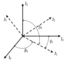
Figure 2 Direction cosines
Two coordinate system defined by marker I (solid line) and marker J (dash line) are shown in Figure 2. Let  be the unit vectors along the
  axes, respectively, and
  be the unit vectors along the
  axes, respectively. Let
  be the angle between
  and
and  ,
,  be the angle between
  and
and  , and
, and  be the angle between
  and
and  . Then the components of the unit vector
  along the
  axes are given by
be the unit vectors along the axes, respectively, and be the unit vectors along the axes, respectively. Let be the angle between and , be the angle between and , and be the angle between and . Then the components of the unit vector along the axes are given by
where  are the direction cosines of the
  axes with respect to
  . In a similar manner, the direction cosines of the
  axes with respect to
  can be denoted as
  , and the direction cosines of the
  axes can be denoted as
  .
.
are the direction cosines of the axes with respect to . In a similar manner, the direction cosines of the axes with respect to can be denoted as , and the direction cosines of the axes can be denoted as .A three-dimensional vector x whose components in the coordinate system  and
and  are denoted as
  and
and  , then one has
  where
where 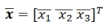 and
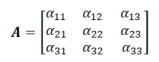
and  , and A is the transformation matrix given by direction cosines matrix as
and are denoted as and , then one has where and , and A is the transformation matrix given by direction cosines matrix as