part create point_mass name_and_position
Allows you to create a point mass by specifying its name and position. You must supply a unique name for the new part, or accept the name that Adams View generates for you.
You define the position of the point mass by:
■Location - You can specify the location by supplying three coordinates corresponding to the current coordinate system type. For example, if the current coordinate system type is Cartesian, you would supply an x, y, and z. You can also specify location by clicking on an existing part or marker that has the same desired location.
■Orientation - You can use the three different methods in Adams View:
♦Orientation
♦Along-axis orientation
♦In_plane_orientation
All location and orientation coordinates are relative to the coordinate system specified in the parameter relative_to.
relative_to defaults to the global origin of the model.
Format:
part create point_mass name_and_position | |
|---|---|
point_mass_name= | new point mass |
adams_id= | adams_id |
comments= | string |
view_name= | existing view |
location= | location |
orientation= | orientation |
along_axis_orientation= | location |
in_plane_orientation= | location |
relative_to= | existing model part or marker |
exact_coordinates= | exact_coordinates |
Description:
Parameter | Value Type | Description |
|---|---|---|
Point_mass_name | New Point Mass | Specifies the name of the point mass to create or modify. |
adams_id | Integer | Assigns a unique ID number to the part. |
comments | String | Adds comments about the part to help you manage and identify it. |
view_name | Existing view | Specifies the view in which to display the part. |
location | Location | Specifies x, y, and z coordinates defining the flexible body's location in a given reference frame defined in the parameter relative_to. |
orientation | Orientation | Specifies the orientation method |
along_axis_orientation | Location | Specifies the orientation method |
in_plane_orientation | Location | Specifies the in_plane orientation method |
relative_to | Existing Model, Part or Marker | Specifies a reference frame relative to which the location and orientation are defined. Leave blank or enter model name to use the global coordinate system. |
exact_coordinates | X, Y, Z, PSI, THETA, PHI, NONE, ALL | Specifies as many as six part coordinates that Adams View is not to change as it solves for the initial conditions. |
Extended Definition:
1. When using the Adams View command language and naming entities, you can use the name later to refer to this entity. Adams View does not allow you to have two entities with the same name, so you must provide a unique name. Normally, entity names are composed of alphabetic, numeric, or '_' (underscore) characters, and start with an alphabetic or '_' character. They may be of any length. For more information, see Using Extended Names.
By enclosing the name in double quotes, you can use other printable characters, or start the name with a numeral. If a name contains characters, or starts with a numeral, you must always quote the name when entering it.
Note that you can specify the parentage of an entity (for example, what part "owns" a marker or a geometry element) when you create it by changing the name. If you enter just the entity name, then Adams View assigns the default parent. If you type in the full name, then you can override the default parent. In most cases, when creating an entity, Adams View provides a default name. The default name that Adams View provides specifies the parentage that it has assumed. You can, of course, delete this name and use your own. The form of a full name is:
"...._NAME.GRAND_PARENT_NAME.PARENT_NAME.ENTITY_NAME"
The number of levels used varies from case to case and the parentage must exist before an entity can be assigned to it.
2. For comments, you can enter any alphanumeric characters. The comments that you create appear in the Information window when you select to display information about the object, in the Adams View log file, and in a command or dataset file when you export your model to these types of files. (Note that design variables are not output to datasets; therefore, neither are their comments.)
3. You can identify an entity, such as a marker or force, by typing its name or by picking it from the screen. If the entity is not visible on the screen, you must type the name. You may also find it convenient to type the name even if the element is displayed.
If an entity is available by default, you can identify it by entering only its name. If it is not, you must enter its full name. To identify an entity under a different part, you may need to enter the model and part names as well. For example, you can specify marker 'pivot' from model 'links', part 'lower_arm' by entering ".links.lower_arm.pivot".
If you type a "?", Adams View lists the entity available by default.
You must separate multiple entity names by commas. If the entity is visible in one of your views, you can identify it by picking it. You need not separate multiple element picks by commas.
Notes: | ■If you created a marker by reading an Adams Solver dataset or graphics file, the marker name is the letters MAR followed by the dataset marker ID number. For example, the name of MARKER/101 is MAR101. If you created the marker during preprocessing, you will have given it a name at that time. ■You may have explicitly named an analysis when you created it by reading one or more Adams output files (graphics (.gra), request (.req), or results (.res)). By default, the name of the analysis is the root name of the Adams output files without the extension. If you created the analysis by reading an Adams graphics file, for example, the analysis name is the name of the graphics file without the .gra extension. |
4. You may identify a view by typing its name or by picking it from the screen. In most cases, you can enter the special view name all, which means all the views currently displayed.
You must separate multiple view names by commas. You need not separate multiple view picks by commas.
5. The along_axis_orientation parameter specifies the orientation of a rigid or flexible body by directing one of its axes. Adams View assigns an arbitrary rotation about the axis. Two points are needed to define an axis but you can enter either one or two points to direct the axis. If you enter two points, the axis points from the first location to the second. If you enter one point, Adams View uses the location you specified in the Location text box as the first point and the new location as the second point.
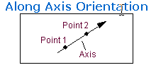
Adams View applies the location coordinates in the coordinate system you identify in the Location Relative To or Relative To text box. Note that this does not completely dictate the orientation of the coordinate system. Adams View positions the coordinate system with an arbitrary rotation about the axis. If you must completely control the coordinate system orientation, select Orientation or In Plane Orientation.
By default, you direct the z-axis of the coordinate system. You can use the DEFAULTS ORIENT_AXIS_AND_PLANE AXIS_AND_PLANE_SETTING command to change this convention. For example, selecting either X_AXIS_XY_PLANE or X_AXIS_XZ_PLANE directs the x-axis. The plane-convention setting does not affect this parameter.
You can also direct the axis graphically using the marker’s position handle. Simply point the appropriate axis on the marker in the desired direction.
6. IThe in_plane_orientation parameter specifies the orientation of the rigid or flexible body by directing one of the axes and locating one of the coordinate planes.
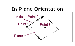
To define an axis and a plane, you need three points. You can enter either two or three locations, however. If you enter three locations, the axis points from the first location to the second and the plane is parallel to the plane defined by the three locations. If you enter only two locations, Adams View uses the location you specified in the Location text box as the first point and the other two locations as the second and third points. Adams View applies the location coordinates in the coordinate system in the Relative To text box. By default, you direct the z-axis of the coordinate system marker and locate the zx plane. You can use the DEFAULTS ORIENT_AXIS_AND_PLANE AXIS_AND_PLANE_SETTING command to change this convention. For example, selecting X_AXIS_XY_PLANE directs the x-axis and orients the xy plane.
7. The six coordinates for the exact_coordinates parameter are:
■X - X coordinate
■Y - Y coordinate
■Z - Z coordinate
■PSI - Psi angle
■THETA - Theta angle
■PHI - Phi angle
You can enter these coordinates in any order. If Adams View has to alter the part position to obtain consistent initial conditions, it does not vary the coordinates you specify with this parameter unless Adams View must vary them to satisfy the initial conditions you specify for a joint or for a motion.