FE PART Results
The FE PART results can be viewed in the Adams PostProcessor. By default, Adams solver generates the results set at each output time step which includes the following entities (for each node):
The generalized coordinates (global position and Euler angles) : X, Y, Z, Psi, Theta, Phi
The generalized velocities (global translational and angular velocities) : Vx, Vy, Vz, Wx, Wy, Wz
The generalized accelerations (global translational and angular acc.) : Accx, Accy, Accz, WDx, WDy, WDz
The elastic/internal forces (in local frame) : Fx, Fy, Fz
The elastic/internal torques (in local frame) : Tx, Ty, Tz
Using these results, the beam stresses and strains are computed.
Recovery of strains and stresses in beams
From the input file, we have the material properties matrix C and the geometric properties of the cross section A, Iyy, Izz and Iyz at each node, where
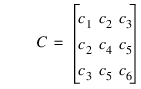
1. If the material is orthotropic, c1 = Ex , c4 = Gxy, c6 = Gxz, and c2 = c3 = c5 = 0, in which Ex is the Young's modulus in the normal direction of the cross section; Gxy and Gxz are the shear moduli of the cross section.
2. If the material is isotropic, c1 = E, c4 = c6 =  , and c2 = c3 = c5 = 0, in which E is the Young's modulus, and v is the Poisson's ratio.
, and c2 = c3 = c5 = 0, in which E is the Young's modulus, and v is the Poisson's ratio.The strain and stress at any particle on the beam are computed using the following steps:
1. From the FE_PART results, we know the force F and torque T of each node in the local frame, and they are calculated using the following formulas
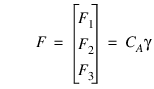 | (1) |
where  is the stretch-shear strain and
  is the torsion-bending curvatures, which are both
  vectors and
is the stretch-shear strain and is the torsion-bending curvatures, which are both vectors and  and
and 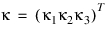 and CA are CI both
  matrices
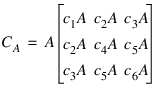 ,
,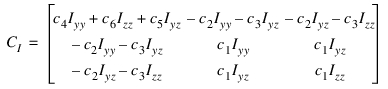
 and
and  at each node can be calculated from the
 2. The stretch-shear strain  and the torsion-bending curvatures
  are continuous along the beam, so
  and
and  at a cross section
  . The strains at a particle with coordinates (s,y,z) can be calculated by
and the torsion-bending curvatures are continuous along the beam, so and at a cross section . The strains at a particle with coordinates (s,y,z) can be calculated by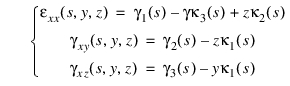
3. The corresponding stress is  with
with 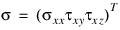 , and the other components are
 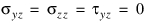 .
.
with , and the other components are .