Working with Flexible Bodies in Suspension Assemblies
In this section, you create a suspension assembly containing flexible lower control arms, learn how to manage the flexible bodies in the assembly, and run an analysis and view its results. You compare the difference in longitudinal wheel displacement by changing the left lower control arm to behave as a rigid body. A flexible body behaves as a rigid body when you set the inertial invariants to rigid.
The following sections teach you how to work with flexible bodies in a suspension assembly:
Creating a Suspension Assembly
You start out by creating a double-wishbone front suspension assembly. This assembly is based on the _double_wishbone template. After opening a suspension assembly, you introduce flexible bodies by performing a rigid-to-flex swap operation.
To create a suspension assembly:
1. Start Adams Car Standard Interface as described in Starting Adams Car Standard Interface.
2. From the File menu, point to New, and then select Suspension Assembly.
Tip: | For information on any dialog box, press F1 when the dialog box is active. |
3. In the Assembly Name text box, enter susp_assy.
4. Right-click the Suspension Subsystem text box, point to Search, and then click on acar_shared and select subsystems.tbl.
5. Double-click TR_Front_Suspension.sub.
Notice that by default Adams Car includes a suspension test rig in the assembly.
6. Select OK.
Adams Car displays the assembly (note that we turned the shading on):
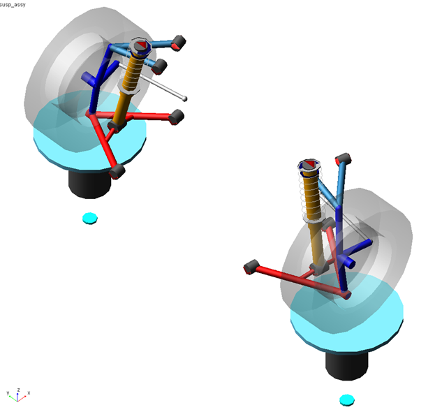
Figure 1 Double-Wishbone Suspension Assembly
At this point the assembly exists only in memory. To save it to disk:
1. From the File menu, select Save As, Assembly.
2. Select OK to save the assembly with all default options, to the default writable database.
Introducing Flexible Bodies
You use the rigid-to-flexible swap functionality to introduce flexible lower control arms to your suspension assembly. Note that you are working on the subsystem (in previous versions, creating flexible bodies meant that you had to create a new template, causing unnecessary template duplication).
To swap the rigid LCA with a flexible body:
1. Right-click ger_lower_control_arm, point to its name, and then select Modify.
2. Select Rigid to Flex.
3. Right-click the text box to the right of MNF File, and search the shared database for LCA_right_tet.mnf.
Adams Car creates a flexible body.
You don’t need to modify the location and orientation of the flexible body, because the MNF was generated using a coordinate system coincident with the rigid part reference frame.
4. Select the Connections tab. You will see a warning message saying that a switch part refers to the rigid body, so it will be deactivated now.
Adams Car fills in the table with all the markers belonging to the rigid part. All the markers will be reassigned (by default) to the closest available node. You can select individual markers by highlighting the row and changing the connection properties.
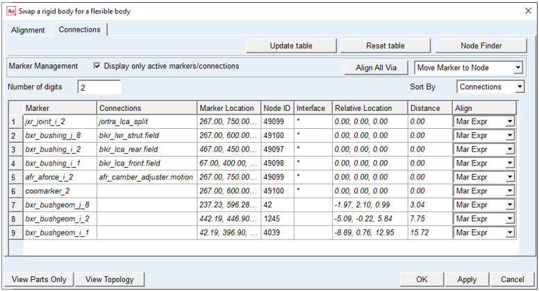
Figure 2 Connections Table
Check the Distance values to ensure that the markers are located near the desired nodes. Notice the Interface column. An asterisk indicates that the closest node was identified as an "interface" node in the FEM representation. This is the recommended approach for nodes at which you apply loads or constraints. For those markers that do not carry a load or constraint, you may wish to omit any node association, thereby assigning those markers' movement to the "rigid body" motion of the flexible body. To do this, select the desired Node ID cell, and remove the node number.
5. Select OK.
Adams Car deactivates the rigid body and replaces it with the corresponding flexible body.
6. Repeat the steps in this procedure for the left part, gel_lower_control_arm, making sure that you select the MNF file named LCA_left_tet.mnf.
Saving the Model
After swapping rigid for flexible bodies, you should save your model. You have several choices at both the subsystem and assembly level, as illustrated in the graphic below.
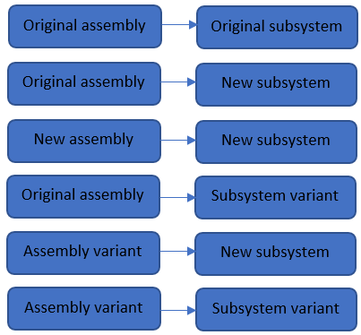
Figure 3 Assembly/Subsystem Save Options
The approach you choose depends on your goals. For example, if you intend to switch back and forth between rigid and flexible bodies depending on the analysis type, we recommend taking advantage of the variant feature as discussed next.
To save your model using variants:
1. From the File menu, select Save As, Subsystem.
2. In the variant option menu, change Existing Variant to New Variant, and type in a name such as "flex_lca" for the subsystem variant name.
3. Click OK to save the subsystem to the default writable database.
4. From the File menu, select Save As, Assembly.
5. In the variant option menu, change Existing Variant to New Variant, and type in a name such as "test_flex" for the assembly variant name. Note that the assembly variant name is independent of the subsystem variant name.
6. Click OK to save the assembly to the default writable database.
Managing Flexible Bodies
Managing flexible bodies involves verifying, modifying, and efficiently using flexible bodies. You can modify flexible body design position/orientation, animate its mode shapes, as well as change flexible body properties.
Displaying Information About Flexible Bodies
You can see if Adams Car correctly imported the flexible body, verify if the rigid-to-flex swap successfully placed the flexible body in the correct location, and display information about the properties that define the flexible body.
To display information about a flexible body:
1. Right-click the left lower control arm part, point to Flexible_Body: TR_Front_Suspension.gel_lower_control_arm_flex, and then select Info.
The Information window appears as shown in the figure below. It lists the inertia properties, the modal contents, and the name of the MNF that Adams Car used when creating the flexible body.
The Information window also shows which mode shapes are active for that flexible body.
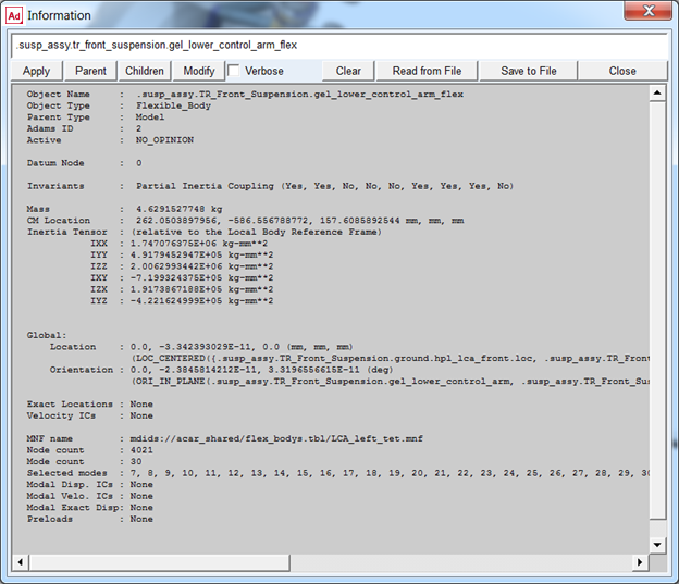
Figure 4 Information Window
2. Select Close.
Displaying and Animating Modes
You can also verify flexible bodies by displaying and animating the modes, and viewing the corresponding frequencies. The Mode Manager is a powerful tool that lets you define a scale factor to emphasize the deformation of the flexible body, animate the flexible part, modify its modal content to improve the efficiency of the simulation, and set initial conditions.
The MNF, as explained in the above sections, contains information about modes and frequencies that define the flexible body.
To view and animate modes:
1. Right-click the left lower control arm part, point to Flexible_Body: TR_Front_Suspension.gel_lower_control_arm_flex, and then select Flex-Body Attributes.
2. In the Mode Number text box, enter 8, and then press Enter.
In the Frequency text box, Adams Car displays the frequency corresponding to mode 8. In the main window, note the bending of the flexible lower arm occurring at approximately 625 HZ.
3. Select Superimpose. This displays the undeformed shape as well as the selected mode shape.
Adams Car highlights the flexible body deformation using color contours (note that we changed the color of the undeformed flexible body to red).
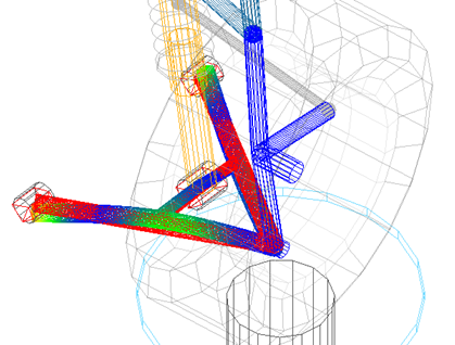
Figure 5 Flexible Body Deformation Using Color Contours
4. Select the Animate tool  .
.
. Adams Car animates the bending mode that the flexible body undergoes at 625 HZ.
Leave the dialog box open, because you will use it again in the next section.
Changing Flexible Body Inertia Modeling
To be able to compare the suspension characteristics between the flexible right and the rigid left side, you will change the inertia modeling of the left lower control arm.
Adams Flex computes the time-varying mass matrix of the flexible body using nine inertia invariants. In particular, four invariant formulations have special significance.
For more information about the invariant formulations, see the Adams Flex online help.
To change the inertia modeling:
1. Set Inertia modeling to Rigid body
2. Select OK.
3. Close the Flexible Body Modify dialog box.
Adams Car disables the 6th invariant, modal mass, and the flexible body becomes equivalent to a rigid part. This causes all the modes to be ignored during the simulation.
Performing a Suspension Analysis
To simulate the flexible body subsystem, you run a suspension analysis and then you review the results, focusing on the flexible body characteristics.
To perform a static load analysis on the suspension subsystem, you define upper and lower braking forces applied at the hub.
To perform a static load analysis:
1. From the Simulate menu, point to Suspension Analysis, and then select Static Load.
2. Fill in the dialog box as shown next, and then select OK.
Figure 6 Performing Static Load Analysis
Adams Car performs the analysis and displays messages about the simulation. The static load analysis simulates the front suspension during a braking maneuver. The change in brake forces causes a longitudinal wheel displacement.
Animating Analysis Results
You animate the results of the analysis to view the deformation of the left rigid arm compared to the right flexible arm. During the animation, Adams Car displays a force vector at the hub.
To animate the results:
1. From the Review menu, select Animation Controls.
2. Select the Play tool  .
.
.Adams Car animates the suspension analysis results. A deformation contour is displayed on the right lower control arm.
Plotting Analysis Results
The flexibility of the right lower control arm affects a series of suspension characteristics that Adams Car computes automatically. You can review the results of these calculations in the plotting environment.
If you submit an analysis in "Interactive" mode, Adams Car automatically loads the analysis results. The results file contains information about the flexible body, as well as any other Adams Solver outputs.
To plot the results:
1. Launch Adams PostProcessor.
2. Verify that Source is set to Requests.
3. From the Simulation list, select tst1_static_load (Adams Car Assembly).
4. From the Request list, select wheel_travel_base.
Note: | Requests are hierarchically arranged under their respective models. You can find wheel_travel_base under the testrig entry. Double-click the plus sign (+) in front of testrig to expand the entry. |
5. From the Component list, select base_left.
6. Set Independent Axis to Data.
7. In the Independent Axis Browser dialog box, from the Request list, select wheel_load_longitudinal.
8. From the Component list, select braking_left.
9. Select OK on the Independent Axis Browser dialog box.
10. Select Add Curves.
11. Repeat Steps 4 through 10, this time selecting the right-side components for wheel_travel_base and wheel_load_longitudinal.
Adams Car plots the longitudinal compliance for the left and right side versus the right longitudinal force at the contact patch.
The plot shows the effect of the flexible body on the displacement of the wheel center due to a longitudinal braking force.
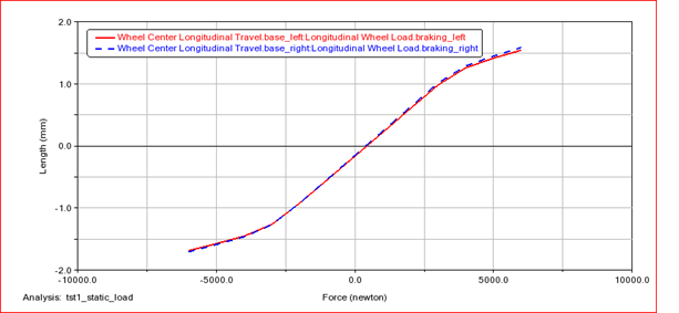
Figure 7 Wheel Center Longitudinal Displacement versus Longitudinal Force
12. Return to Adams Car.