Working with Flexible Bodies in Full-Vehicle Assemblies
In this section, you perform a full-vehicle maneuver and focus on the flexible part characteristics. Before you can perform the maneuver, you must create a full-vehicle assembly.
You perform these operations in the following sections:
Creating a Full-Vehicle Assembly
To create the assembly:
1. From the File menu, point to Open, and then select Assembly. Right-click in the Assembly Name field, select Search, then <acar_concept>/assemblies.tbl. Double-click on sedan_RWD.asy and hit OK.
2. Select File, Manage, Assemblies, Replace Subsystem, and fill out the dialog as shown in Figure 8 below.
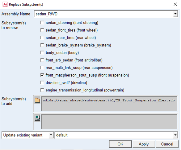
Figure 8 Replacing the front suspension subsystem
Adams Car displays the full-vehicle assembly, as shown next:
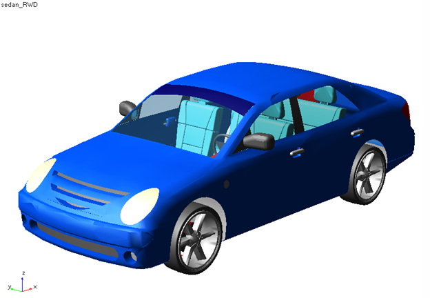
Figure 9 Display - Full-Vehicle Assembly
Integrating Flexible Bodies
In this section you will perform the following tasks:
Swapping MNFs
If the FEM expert produced the lower control arm modal neutral files maintaining the same node number for the attachment points, you can easily swap the flexible body (modal neutral files) and maintain the parameterization. You can replace the flexible body by selecting a different MNF provided in the shared database. This is analogous to replacing a damper or spring property file.
To swap the MNF:
1. Double-click the left flexible lower control arm, fbl_lower_control_arm.
The Modify Flexible Body dialog box appears.
2. Right-click the Modal Neutral File text box, point to Search, and then select the acar_shared database.
3. Double-click LCA_left_tra.mnf.
4. Select Apply.
5. Right-click the Flexible Body text box, point to Flexible Body, point to Pick, and from the screen, select the right lower control arm, fbr_lower_control_arm.
6. In the Modal Neutral File text box, enter LCA_right_tra.mnf.
7. Select OK.
Adams Car replaces the flexible lower control arm that was originally modeled using shell elements in the FEM environment, with beam elements. Moreover, the lca_front hardpoint now has a different location, but Adams Car has maintained the parameterization of the model, and the topological information is correct. This is because Adams Car uses interface parts to connect flexible bodies with the rest of the model. Interface parts are a special class of general parts that are parameterized to the locations of the node numbers. When the locations of the node numbers move, the interface parts and the rest of the model move accordingly. Node numbers are defined in the MNF and cannot be changed in Adams Car.
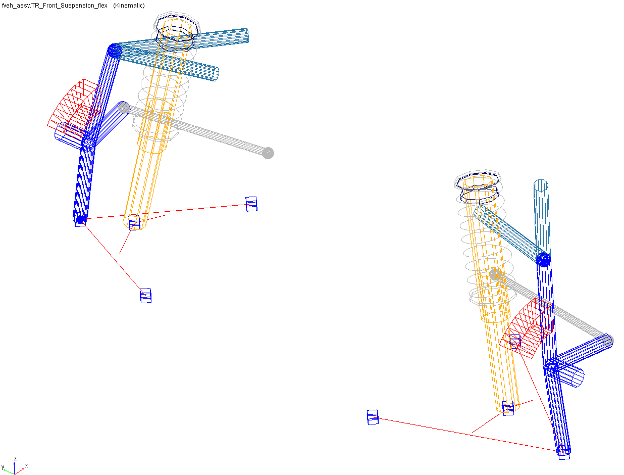
Figure 10 Modified Flexible Lower Control Arm
Changing Modal Content
By default, when you integrate an MNF into an Adams Car template, Adams Flex enables all the modes that were defined during the FEM modeling except the probable rigid body modes (modes one through six). It is important to have the right modal content in flexible bodies, because an MNF may have more modes than are needed to simulate a particular response, and the number of active modes drives the computation time.
To increase the efficiency of the simulations, you should disable any modes that do not contribute to the motion that your flexible part will undergo during the simulation. Be careful when disabling modes, because a disabled mode corresponds to a constraint to the part.
You can enable and disable modes in several ways:
■Individually, based on their mode number.
■As a group, based on their mode number or frequency.
■Through a table editor. The table editor also lets you define displacement and velocity initial conditions associated with every mode.
■Based on their strain energy contribution, but you can only do this after a successful analysis. For more information on this technique, see the Adams Flex online help.
To disable individual modes:
Some of the modes of the flexible lower control arms do not contribute significantly to the dynamic behavior of the system. We recommend that you disable them to reduce the computational effort and to improve the efficiency of the simulation.
You must disable these modes for both the left and the right side because a left and a right MNF defines the flexible lower control arms.
1. Zoom in on the front suspension.
2. From the Adjust menu, point to Flexible body, and then select Mode Manager.
The Flexible Body Modify dialog box appears.
3. Right-click the Flexible Body text box, point to Flexible body, point to Pick, and from the screen, select the left lower control arm, fbl_lower_control_arm.
4. Select Modal ICs.
The Modify Modal ICs dialog box appears.
5. Hold down the Shift key, select modes 35 and 36, and then select Disable Highlighted Modes.
6. Close the Modify Modal ICs dialog box.
7. Repeat Steps 3 through 6, for the right lower control arm, fbr_lower_control_arm.
8. Close the Flexible Body Modify dialog box.
Save the Model
To save your model using variants:
1. From the File menu, select Save As, Subsystem.
2. In the Subsystem Name option menu, select TR_Front_Suspension_flex.
3. In the variant option menu, change Existing Variant to New Variant, and type in a name such as "beam_lca" for the subsystem variant name.
4. Click OK to save the subsystem to the default writable database.
5. From the File menu, select Save As, Assembly.
6. In the variant option menu, change Existing Variant to New Variant, and type in a name such as "beam_element_front_lca" for the assembly variant name. Note that the assembly variant name is independent of the subsystem variant name.
7. Click OK to save the assembly to the default writable database.
Performing a Full-Vehicle Analysis
You are now ready to perform the full-vehicle analysis. After you perform the analysis, you can switch variants to compare the effect of the chosen MNF on the dynamics of the vehicle.
To perform the full-vehicle analysis:
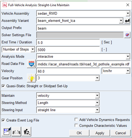
1. From the Simulate menu, point to Full-Vehicle Analysis, point to Straight-Line Events, and then select Maintain.
2. Set up the analysis as shown below:
3. Select Apply, so the dialog box stays open for the analysis you will run in the next section.
You may wish to animate the results.
Submit another full-vehicle analysis:
1. In the Assembly Variant option menu, select default.
2. For Output Prefix, enter "shell".
Select OK to run the analysis with the original shell element lower control arm representation.
Plotting Analysis Results
In this section, you create a set of plots that show the behavior of your vehicle assembly and then review how the lower control arm representation affects the overall dynamics of the vehicle.
To plot the results:
1. Launch Adams PostProcessor.
2. From the Plot menu, select Create Plots.
3. Fill in the dialog box as shown next, and then select OK.
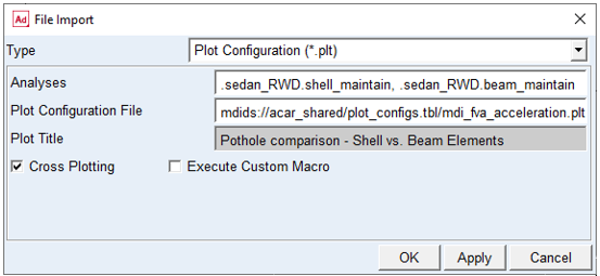
Figure 11 Plot File Import
4. Examine the plots to determine the effects of the lower control arm representation. Figure 12 shows one of the plots.
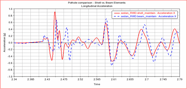
Figure 12 Chassis Longitudinal Acceleration