Analyzing an Assembly Containing Your Template
In this section, you perform two types of suspension analyses and plot the results.
We assume that you already completed the previous tutorials, and know how to incorporate your new template into an analysis.
You perform the following types of analyses:
Performing a Kinematic Analysis
When you perform a kinematic analysis, you use the joints, rather than the bushings, that you defined when you built your template.
Before you can perform the kinematic analysis, you must create a suspension assembly. After you create the suspension assembly, define a preload.
To create a suspension assembly:
1. From the File menu, point to New, and then select Suspension Assembly.
2. In the Assembly Name text box, enter susp_assy_1.
3. Verify that Suspension Subsystem is set to the name of your subsystem, my_macpherson. If it is not, click the folder icon next to Suspension Subsystem.
The name of your subsystem, my_macpherson, appears next to the icon.
4. Select OK.
5. When Adams Car finishes creating the assembly, select Close.
To define a preload:
1. Right-click either spring, point to the name of the spring, and then select Modify.
2. Set Installed Length to 135.0.
3. Select OK.
To change to kinematic mode:
1. From the Adjust menu, select Kinematic Toggle.
The Toggle Kinematic Mode text box should already contain the name of your subsystem.
2. Set Current Mode to Kinematic.
3. Select OK.
To perform a kinematic suspension analysis:
1. From the Simulate menu, point to Suspension Analysis, and then select Parallel Wheel Travel.
2. Fill in the dialog box as shown next, and then select OK.
Adams Car performs the analysis and displays messages about the simulation.
3. When the analysis is complete, select Close.
To animate the results:
1. From the Review menu, select Animation Controls.
2. Select the Play tool  .
.
.The suspension animates through full jounce and rebound.
To plot the results:
1. Launch Adams PostProcessor just as you did in Plotting Results.
2. From the Plot menu, select Create Plots.
3. Set up the plots as follows:
■Plot Configuration File: mdids://shared_acar/plot_configs.tbl/mdi_suspension_parallel_travel.plt
■Plot Title: My MacPherson
4. Verify that Cross Plotting is not selected.
5. Select OK.
Adams Car automatically generates a series of plots based on this plot configuration file.
6. Cycle through the plots using the plot navigation tools.
Figure 3 shows the Toe Angle plot.
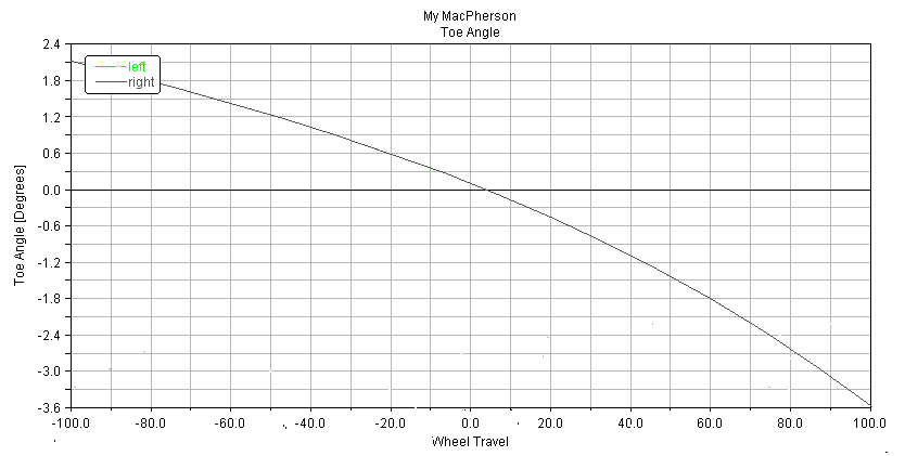
Figure 3 Plot of Toe Angle - Kinematic Analysis
7. After viewing the plots, return to Adams Car.
Performing an Elasto-Kinematic Analysis
To run an elasto-kinematic analysis, you must first switch the mode from kinematic to compliant. This turns off kinematic constraints and uses bushings for attachments between the parts.
Next, you must modify analysis parameters, and then run the analysis.
After the analysis is complete, you return to Adams PostProcessor to compare analysis results.
To change to compliant mode:
1. From the Adjust menu, select Kinematic Toggle.
2. Set Current Mode to Compliant.
3. Select OK.
To perform an elasto-kinematic analysis:
1. From the Simulate menu, point to Suspension Analysis, and then select Parallel Wheel Travel.
2. Set the Output Prefix to ela.
3. Select OK.
Adams Car performs the analysis and displays messages about the simulation.
To plot the results of the elasto-kinematic analysis:
1. In Adams PostProcessor, set up the comparison plots as follows:
■Plot Configuration File: mdids://acar_shared/plot_configs.tbl/mdi_suspension_parallel_travel.plt
■Plot Title: My MacPherson
2. Select Cross Plotting.
3. Select OK.
Adams Car creates plots with both analyses results included on each plot.
Figure 4 shows a comparison plot for the toe angle.
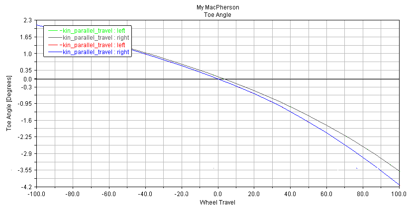
Figure 4 Toe Angle - Comparison Plot
Note that the elastic toe angle is greater than the toe angle as measured in kinematic mode.