Performing a Quasi-Static Constant-Radius Cornering (CRC) Analysis
You use a CRC analysis to evaluate your full vehicle’s understeer characteristics. The CRC analysis holds the turn radius constant and varies the vehicle’s lateral acceleration. A control subroutine, CONSUB, controls the analysis and balances all the forces on the body and applies a lateral acceleration to all model parts.
Submit a CRC analysis and view the results as explained in the following sections:
Setting Up the Analysis
You can now specify the inputs for the full-vehicle analysis and perform a quasi-static maneuver.
To set up the analysis:
1. From the Simulate menu, point to Full-Vehicle Analysis, point to Static and Quasi-Static Maneuvers, and then select Constant Radius Cornering.
2. Run an analysis with the following specifications:
■Output Prefix: fveh
■Number of Steps: 30
■Final Lateral Accel: .9
■Turn Radius: 50
■Set the units pull-down menu for the turn radius to m.
3. Select OK.
Adams Car updates the properties of force entities such as dampers, springs, and bushings, with the values specified in their property files and sets up the vehicle assembly for the maneuver.
The number of steps for the output is directly related to the acceleration increment (that is, acceleration increment = final lateral acceleration / number of steps). Adams Car performs a static analysis at each lateral acceleration increment. When the vehicle reaches the specified final lateral acceleration, the maneuver ends automatically or if the vehicle’s lateral acceleration limit is less than the final lateral acceleration, Adams Solver reports failures and stops the maneuver.
Animating and Plotting the Results
In this section, you view the results of the analysis you just ran. Adams Car has already loaded the analysis results files for you. Before you animate, you should change the magnification of your assembly so you can see the path the vehicle is taking.
After you animate, create plots using a plot configuration file (.plt), as explained next.
To create plots associated with the maneuver:
1. Launch Adams PostProcessor.
2. From the Plot menu, select Create Plots.
3. Right-click the Plot Configuration File text box, point to Search, and then select the acar_shared database.
4. Double-click mdi_fva_ssc.plt.
5. Select OK.
You have automatically created a series of plots associated with this type of maneuver. Adams PostProcessor displays the first plot, as shown next:
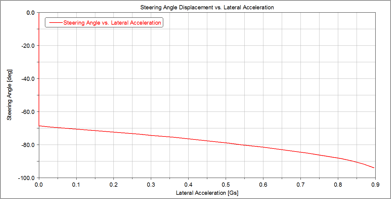
Figure 4 Plot of Steering Angle versus Lateral Acceleration
6. To view the rest of the plots, select them from the treeview. For example, to view the second plot, select page_plot_2.
Adams Car displays a plot of the chassis roll angle versus lateral acceleration.
7. Return to Adams Car.