Step Two - Creating the Adams Plant Inputs and Outputs
Now you’ll create the inputs and outputs on the Adams model by:
Identifying the Adams Plant Inputs and Outputs
Figure 2 indicates the flow path of the input and output variables shared between the antenna model and its control system. This diagram shows that when you supply an input control torque to the antenna model, you send outputs azimuth_position and rotor_velocity to the controller.
The steps you follow to achieve this closed-loop circuit are:
■Define the input and output variables in Adams View.
■Read in the plant and the input/output variables using Easy5 or MATLAB, create an Adams plant, and run a simulation.
■Animate and plot the simulation results in Adams View.
■Modify the variables and repeat this process as necessary.
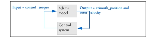
Figure 2 Terminology for Adams Inputs and Outputs
Verifying Input Variables
Adams Controls and controls applications, such as Easy5 and MATLAB, communicate by passing state variables back and forth. Therefore, you must define your model’s input and output variables (and the functions that those inputs and outputs reference) with a set of Adams state variables.
This step has already been done for you in the antenna model that you imported. When you create a model of your own, you will have to define the state variables for your input and output variables.
For this tutorial, you will only verify that the state variables in the antenna model and control system correspond to the correct input and output variables. For a description of state variables, see the online help.
To verify the input variables:
1. From the Model Browser window, click Elements and expand.
2. Expand System Elements.
3. Double-click control_torque.
The Create/Modify State Variable dialog box appears.
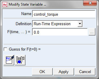
Figure 3 Modify State Variable Dialog Box
4. Look in the F(time, ...) = text box and verify that the run-time function for the input variable, control_torque, is 0.0.
Because the control torque will get its value from the control application, the 0.0 will be overwritten during each step of the simulation.
5. Select Cancel to close the Modify State Variable dialog box.
Note: | After you close the box, click in the background of the screen to clear the selection of the model. |
Verifying Input Functions
Now you’ll verify the function that references the input variable.
To verify the function that is referenced to the input variable control_torque:
1. From the Edit menu, select Modify.
The Database Navigator appears.
2. Double-click main_olt, and then double-click azimuth_actuator (azimuth_actuator is the name of the control torque).
The Modify Torque dialog box appears.
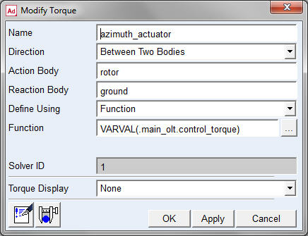
Figure 4 Modify Torque Dialog Box
3. Look in the Function text box and verify that the run-time function for the input variable reads: VARVAL(.main_olt.control_torque).
Note: | VARVAL (variable value) is the Adams function that returns the value of the given variable. Notice that the function is defined as the value of the control_torque variable. In other words, the input control torque (azimuth_actuator) gets its value from the input variable. |
4. Select Cancel to close the Modify Torque dialog box.
Verifying Output Functions
Now you’ll verify the output functions just as you verified the input functions in the previous section.
To verify the output functions:
1. From the Model Browser window, click Elements and expand.
2. Expand System Elements.
3. Double-click azimuth_position.
The Create/Modify State Variable dialog box appears.
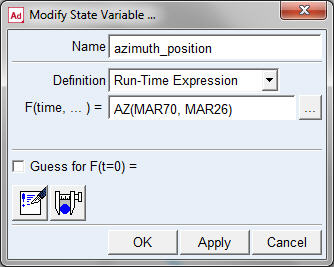
Figure 5 Modify State Variable Dialog Box
4. Look in the F(time, ...) = text box to verify that the run-time function for the output variable is AZ(MAR70, MAR26).
This function returns the angle about the z-axis, the vertical axis about which the antenna rotates. Therefore, the function assigns the rotational position of the antenna to the output state variable.
5. Right-click the Name text box, point to ADAMS_Variable, point to Guesses, and then select rotor_velocity.
The Modify State Variable dialog box updates.
6. Look at the F(time, ...) = text box and verify the run-time function for the output variable is WZ(MAR21, MAR22, MAR22).
This function measures the rotational velocity of the rotor relative to ground.
7. Select Cancel to close the dialog box.
Exporting the Adams Plant Files for the Controls Application
In this section, you will export the Adams linear and nonlinear plant files.
To export the nonlinear plant files:
1. From the Plugins tab, click on the Controls container and select Plant Export.
The Adams Controls Plant Export dialog box appears.
2. In the New Controls Plant text box, enter ant_test.
3. In the File Prefix text box, type ant_test for the filename.
This defines the prefix for the .adm, .cmd, .m, and .inf files created by the Plant Export dialog box.
4. Right-click the Input Signal(s) text box, point to ADAMS_Variable, and then select Browse.
The Database Navigator appears.
5. In the Database Navigator, select control_torque, and then select OK.
6. In the Adams Controls Plant Export dialog box, right-click the Output Signal(s) text box, point to ADAMS_Variable, and then select Guesses.
A selection list appears.
7. From the selection list, select rotor_velocity.
8. Repeat Step 6, and then from the selection list, select azimuth_position.
Note: | It is important to maintain the above selection order for selecting output signals so that the model works properly with the example MATLAB or Easy5 model. |
9. From the Target Software pull-down menu, select the controls application you are using during this session: MATLAB or Easy5.
10. Confirm that Analysis Type is set to non_linear and Initial Static Analysis is set to No.
Note: | If Analysis Type is set to linear and Initial Static Analysis is set to Yes, Adams Controls conducts a static analysis before the linear analysis. Otherwise, Adams Controls performs an initial conditions analysis. |
11. Verify that the Adams Solver choice set as desired and Adams Host Name is set to your machine name.
Be sure that the name for Adams Host is a fully qualified hostname or localhost if using TCP/IP communication with co-simulation or function evaluation mode. This is not required for PIPE-based communication. (To be fully qualified, the hostname must contain the workstation and domain name.) If the Adams Host is not fully qualified, edit the value in the text box so that it is fully qualified.
12. If Target Software is set to Easy5, verify that Dynamic States Output is selected.
Dynamic States Output performs an initial conditions analysis or a static analysis (if Initial Static Analysis is set to Yes), and computes the number of states (that is, displacements, velocities) in the model. This is used by Easy5 for Function Evaluation mode. If your model has difficulty computing this properly, you can disable this feature, but you will not be able to use Function Evaluation mode unless the number for NUMBER OF STATES is modified in the .inf file from Plant Export.
13. Verify that the Plant Export dialog box is completed as shown in the figure below.
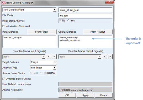
Figure 6 Adams Controls Plant Export Dialog Box
14. Select OK.
Adams Controls saves the input and output information in an .m (for MATLAB) or .inf file (for Easy5). It also generates a command file (.cmd) and a dataset file (.adm) that are used during the simulation process. Empty file called aviewAS.cmd is also created which will prevent the startup screen from displaying when simulating interactively with Adams View.
Note: | The ant_test Controls Plant you just created is saved in the modeling database. By importing settings from an existing plant, you can generate new plants based on plants you already created. |
To export the linear plant files (optional: not required for co-simulation or function evaluation):
1. From the Plugins tab, click on the Controls container and select Plant Export.
2. In the Adams Controls Plant Export dialog box, create a new controls plant by importing settings from a previous plant.
3. Change the file prefix from ant_test to ant_test_l.
4. Set Analysis Type to Linear.
5. Set Initial Static Analysis to Yes.
6. Select OK.
Adams Controls generates the linear model of the Adams model in four matrices: ant_test_la, ant_test_lb, ant_test_lc, and ant_test_ld.
Adams Controls setup is complete after the plant files have been exported. Now you will go to the specific controls application (Easy5 or MATLAB) and complete the link between the controls and mechanical systems.
Notes: | You have now finished the introduction to the Adams Controls tutorials. To continue learning the Adams Controls interface, go to the tutorials that follow this section. If you are using: ■MATLAB Co-Simulation or Function Evaluation, go to Learning Adams Controls with MATLAB Co-Simulation/Function Evaluation. ■Control System Import with MATLAB, go to Learning Adams Controls with Control System Import from MATLAB. ■Control System Import from MATLAB with S-Functions, go to Learning Adams Controls with Control System Import from MATLAB with S-Functions. ■Easy5 Co-Simulation or Function Evalutation, go to Learning Adams Controls with Easy5 Co-Simulation/Function Evaluation. ■Control System Import with Easy5, go to Learning Adams Controls with Control System Import from Easy5. |